VFD Clock
This project has been paused indefinitely: Please see this blog for a continuation of VFD display work: https://hannahmishin.com/blog/2017/4/30/russian-tri-color-vfd-indicator-clock.
So, while I was in Ohio for the Holography Residency, I toured some surplus places.
At Fair Radio (http://www.fairradio.com/) in Lima, OH, I came across some circuits from old calculators (circa 1981).
IF YOU EVER FIND YOURSELF IN OHIO, DO TAKE A DETOUR THERE! (like for real)


I decided to make a clock. Standard fare for these tubes, but none-the-less, an interesting project.

________________________________
So what is a VFD?
Vacuum Fluorescent Display

All segments are common anode.
The types of VFD is a ISEDEN DG12C.
There is no Datasheet on the internet. But I pieced it together:
The cathode gets +1vdc on one side and 0vdc (pos and ground).
The grid gets +24vdc
and each segment gets +24vdc to light
Here's a good image of the electrical wire guide:

___ The leads on these guys are fragile. I recommend - straight away- stabilizing the leads, or removing the solid-core wires (old-as-all) with some fresh rainbow cabling.

(my little mock up guy)
There are a ton of tutorials out there using transistors and other types of drivers to power their VFDs. I believe that the cost of the VFD chips is way higher than a Darlington Array, for example. I felt that the Approx. 5 dollar chip would save me in other circuitry (therefore circuit area, and on coding issues).
So, instead of making my own VFD driver out of transistors, I chose, instead, to use a VFD driver chip.
http://www.mouser.com/ds/2/256/MAX6920-107249.pdf
These are SMD chips; So I got some SMD Chip breakout boards from Adafruit (cheapest!)
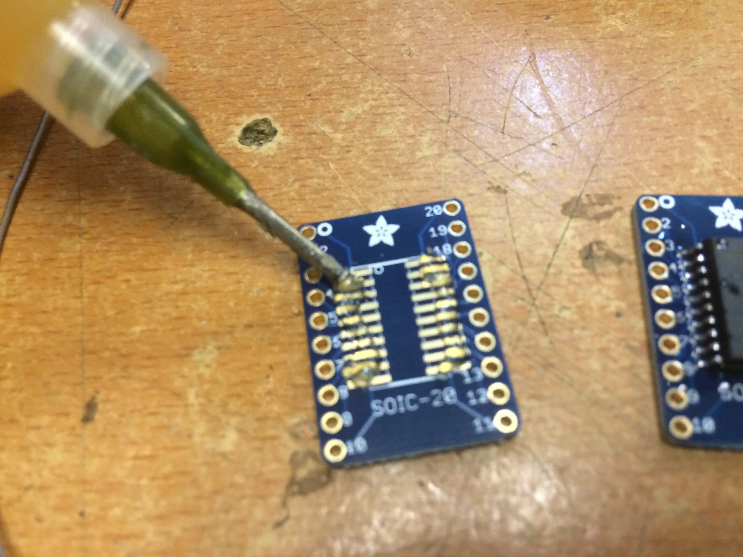
As these are 12 segment displays but the leads to everything not a part of a standard 7-segment display are very very hard to solder leads to.
In my design, I require a 6 tube display: hour - dash - minute -letter "A" or "P"
(# # : # # A/P)
REFERENCE MATERIAL
Here is a good tutorial on how to make Multidimensional Arrays:
https://programmingelectronics.com/tutorial-24-multi-dimensional-arrays-aka-matrix-old-version/
I also found this library written by the Nortitake company (the company which manufactured the tubes I am using) :
A good tutorial on how to pair code and circuits==
https://arduinotehniq.blogspot.ro/2016/08/itron-fg209m2-vfd-display-controlled-by.html
http://www.noritake-itron.com/subpages/applicnotese/vfdoperapn.htm
http://www.explainthatstuff.com/how-vacuum-fluorescent-displays-work.html
GETTING STARTED >>> HOW DO THESE THINGS DO?
I applied voltage to the filament (see video above to explain variables in voltage on the filament)- I applied 52.6VDC to the Grid Mesh, and the same voltage to a segment of the display. I acquired a buck booster for this High Voltage DC.
Below is an image of the filament and segment/grid voltages for this test.

The three grey lines coming off the tube represent the filament and the grid/mesh. These corresponded to three colored leads coming off the iseden itron tube. The red stripe on the grey wires is the mesh.

I wired all of the VFDs in the same order - meaning each lead has been sequentially set for every VFD I have. (i.e. Red lead is the same segment on all VFDs). Therefore, I must create my own library to pass the bits through.
i.e. writing to a VFD as numerical value 7, for my wiring I send :
{ 1, 1, 1, 0, 0, 0, 0, };
In order to make this seamless, and the code not so arduous, I put the values representing the each number inside a multidimensional array.
The MA6920 pinouts do not like data which is not to the size of its output capacity (12 outputs).
i.e. write to a VFD as numerical value 7 via the MAX6920, I must send 12 values { 1, 1, 1, 0, 0, 0, 0, 0, 0, 0, 0, 0, };
In addition, as I was testing my code- I noticed several of my VFDs began to dim in brightness. It is crucial to the life expectancy of the VFDs that they go off and on (persistence of vision will help us here).
There are several ways to ensure that the segments go off and on.
I can write DataIn Pin LOW after sending Load HIGH - I can also turn the grid/mesh ON/OFF with a transistor.
This last bit (grid ON/OFF) introduces a new way to drive the VFDs with the same chip
MULTIPLEXING VS. BIT SHIFTING:
The MAX6920 is a chip which shifts data from chip to chip.
The VFDs can Multiplex, as they natively support ON/OFF functionality via the grid/mesh, as when the grid/mesh is not powered, the VFD is off.
BIT SHIFTING>>>>
The original plan was to utilize the DOUT functionality of the MAX6920 chips. I had problems passing reliable arrays through the pins.
So I've decided to setup unique Data In pins and unique Clock pins, but still daisy-chaining the BLANK and the LOAD pins as designed by the Maxim chip.
This means I have a unique array for the first chip, and so on for the four chips required to drive six tubes, all containing 12 bits.

I have four MAX6920 chips
Each Chip has DataIn, Clock, Load, DataOut, and Blank -
The DataIn pin (19), accepts the bits (send the array)
The Clock pin (11) clocks these bits to the chip on the rising edge (meaning, every time you want to display the bit, you have to turn the clock HIGH - and then LOW as before you want to move onto the next bit to display)
- i.e. - DATAIN - 1bit - CLOCK HIGH -CLOCK LOW
The Load pin (12) pushes the bits to the segment (i.e. turns the display on) when HIGH. Make the Load pin LOW before reading new data (like a bang).
-i.e.- cycled through all bits in the above step and then -LOAD HIGH -LOAD LOW
The Blank pin (9) resets the Clock and Load when HIGH.
MULTIPLEXING>>>>
Nortitake recommends, when multiplexing, that the VFD segments and the grid get breaks from constant voltage.
So, I can use only seven pinouts from a singular VFD chip, and just overwrite the data. When the code is cycling through to the next seven segments, I turn the grid on for that tube.
One PNP transistor per tube and One MAX6920 chip for all tubes.
Persistence of vision means - it will be unseen -
So I hooked up the MAX6920 to two VFDs and gave them two different arrays to displays
MULTIPLEXING CIRCUIT NOTES with MAX6920 CHIP>>>>>
The transistor began behaving inappropriately when I began moving the circuit from the breadboard to a perf-board. It is a PNP, as all I have to control with the grid is positive voltage.
Therefore, in using a PNP, I am switching power on and off. In setting up this on a breadboard, I ran aground of some issues. There is a relationship of resistor to transistor to load to power. So I have to do some math.
Here is a decent video explaining (with an NPN example) how transistors work (extracted from a sparkfun tutorial on transistors ):

PNP - put a transistor on the base.
I did the calculations based on a 2N3906, and found a website which offers to do the math for me - to determine the Base resistor value.
http://kaizerpowerelectronics.dk/calculators/transistor-base-resistor-calculator/
According to this calculation (included in the load values is a 100mA LED + the Grid of the VFD. 2.2K Ω
(*note*- the above link shows a NPN transistor, In reading, these calculations should be the same for a PNP)
Knowing that the transistor sends current from emitter to the base....that resistor needs to consume any back voltage but be small enough to send the signal through.


What ends up happening if the resistor is not accurate, the voltage not consumed by the resistor ends up being added to the signal voltage when forward current is applied.
-- The PNP transistor needs a higher Voltage on the Base than what is on Collector to reach Saturation (i.e. ON).--
Therefore I need to use a NPN to accept a TTL voltage on the base of the NPN (switching ground) to saturate the Base of the PNP.
As in this link:
http://electronics-diy.com/schematics/1012/Driving_P-Channel_MOSFET.gif
TRANSISTOR LINKS:
MULTIPLEXING ARDUINO CODE with MAX6920 CHIP>>>>>>
This code is merely testing that the comparison of VFDdis array (a placeholder that the RTC will populate) successfully reads and translates any values 0-9 to display.
---CODE CONTINUED>>>>>>>
I want several functions included in the clock, including the usual, and typical - manual time change.
I coded this display and function:
The only variable to change the display is the "pace" delay function when writing to the VFDs.
if (editMode == true){
pace = 40;
}
if (editMode == false){
pace = 1;
}
digitalWrite (load, HIGH);
digitalWrite (load, LOW);
digitalWrite (grid[0], HIGH);
delay(pace);
digitalWrite (grid[0], LOW);
digitalWrite(din, 0);
CODE FINISHED- implemented a string when a random hourly rollover occurs!
See here for completed code. Mostly debugged.
https://github.com/hannahmishin/VFD_full_function/tree/master
POWER-
There are 4 power requirements for this project:
* The filament power - .9V
The Nortitake Sheets mention that the Filament would like to have AC voltage. As I do want this to be somewhat compact, I will explore generating an AC in with a capacitor and a TONE function from Arduino. This may or may not be required.
* The mesh/grid power AND the input voltage to the Buck Booster AND the Arduino Power - 12V @ approx .55A
* The TTL Power for the logic pins on the chip (Arduino generates for free)
* The High Voltage for the annodes of the VFDs - 35V (off buck booster)
I need to power all of these from one wallwart @ 12VDC. So, I need to calculate dropdown resistors and/or voltage regulators and see if anything needs heatsinking.
Doing the calculations, I need a 120KΩ/1W resistor - pulling from the 12VDC supplying the buck booster to create the .9v @ .08a per VFD
The VFDs themselves do not draw a lot of amperage. Therefore using a Buck Booster :
The buck–boost converter is a type of DC-to-DCconverter that has an output voltage magnitude that is either greater than or less than the input voltage magnitude. It is equivalent to a flyback converter using a single inductor instead of a transformer.
I got a cheap module off of Amazon.com - though I fear it is too large for the enclosure I intend to build.
https://www.amazon.com/gp/product/B00QZYX8KE/ref=oh_aui_detailpage_o02_s00?ie=UTF8&psc=1

It functions fine, and provides a stable enough boosted supply voltage.
However, after my testing process has begUn (leaving the system plugged in over a significantamount of time to confirm no damage to the tubes at the frequency I pulse them), I want to run the tubes off of a smaller Booster - I now know that I do not need more then 35v (purchased the above one, on the assumption that I would need 60-75 v). It works really well and at such a smaller footprint!
https://www.amazon.com/gp/product/B00J1X4XXM/ref=oh_aui_detailpage_o00_s00?ie=UTF8&psc=1

ARDUINO INTEGRATION CIRCUIT>>>>
As I am tight on space, and as I am making a board anyway, I've decided to integrate an RBB Arduino (from Modern Device: https://moderndevice.com/product/rbbb-kit/ )
which provides design files for download:

I use eagle CAD for circuit design, so, I looked to see if anyone awesome had already done the work to convert the above files to an eagle friendly version, and yes, this instructable provided files:
http://www.instructables.com/id/Single-Sided-Really-Bare-Bones-Board-Arduino-in-EA/
You can purchase bootloaded ATMEGA328 chips, but they cost about 5 dollars each
However, Adafruit offers an awesome tutorial on how to make your own bootloader, wherein you can buy just the ATMEGA328 chip for 3 dollars. So, if you are planning on doing more than just a few of these, it might be prudent to follow the Adafruit build:
https://learn.adafruit.com/arduino-tips-tricks-and-techniques/arduinoisp

I have some of these RBB Arduinos from Modern Device, so in my prototyping phase, I am testing that my code and circuit will be able to run off this device.

ELECTRONICS ASSEMBLY>>>>>>>

Testing that the PCB works

Tinning the PCBs
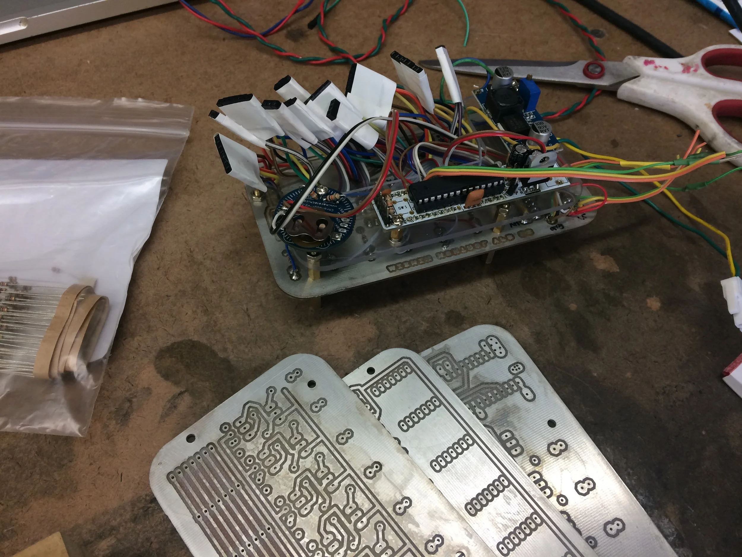
Hooking up the headers

Using superglue to secure wiring (the small gauge wires tend to snap on the board - superglued leads to keep them from breaking) BEST SUPERGLUE EVER

Prepping the RBBBs and other breakouts
The circuit Design Files Link is here (Eagle SCH file, and AI vector file):
https://www.dropbox.com/sh/wt0xfw0f134puta/AAAaEGqRoYbEAwi-dZwwDjnya?dl=0
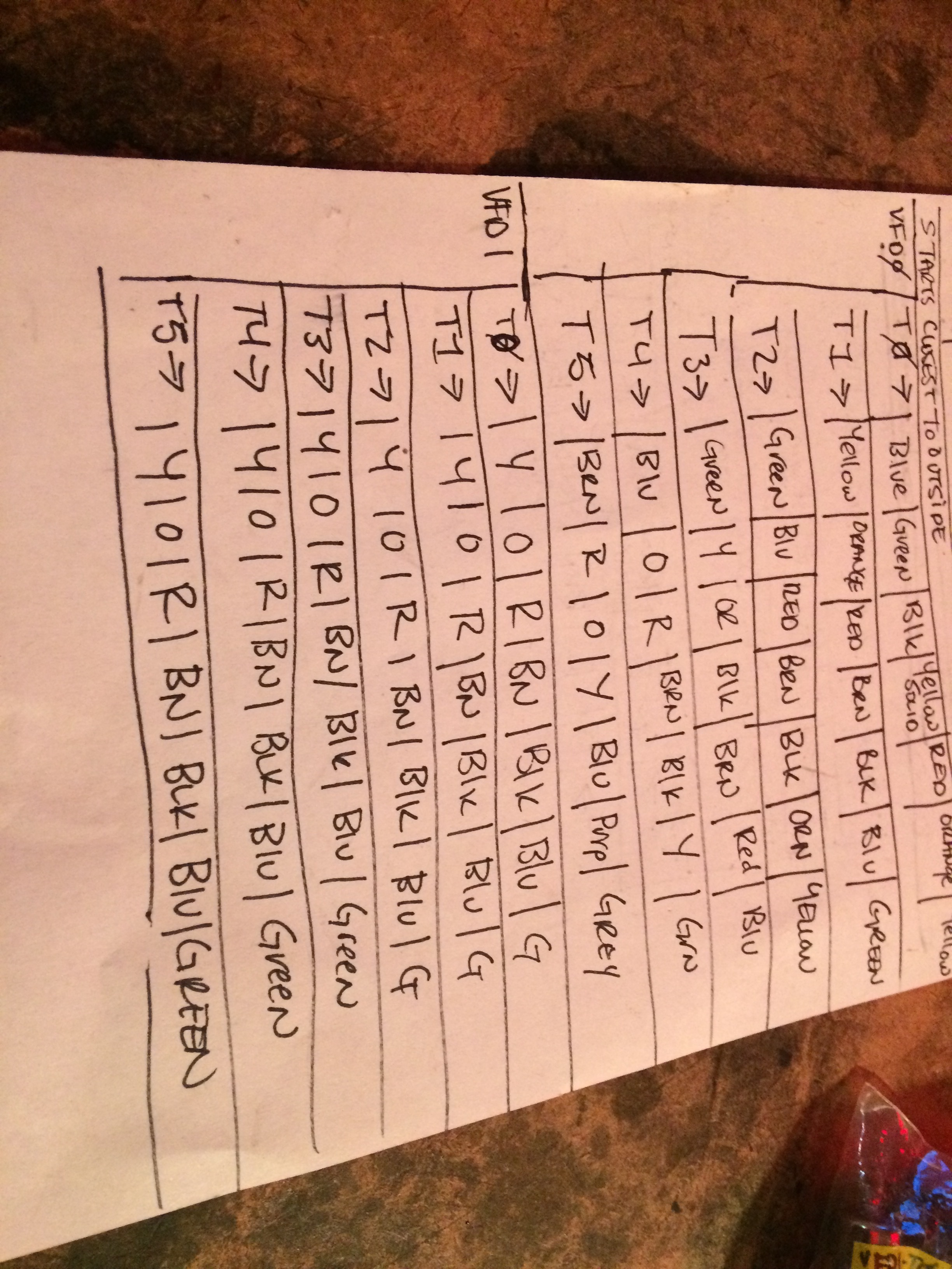
Color wiring guide per board

Wiring Guide for Arduino
PCB MANUFACTURE>>>>>
The VFDs began acting strangely. I looked around at other examples of VFD Driver circuits, and could not find evidence that I left out crucial components. Therefore, I feel that the home-made PCBs have created an a-stable circuit (no vias nor plated through-holes were available options).
So I uploaded the gerber and drill files with PCBway.
CHRONODOT RTC>>>>>

Ran this code after downloading the RTClib library ::
*notes: SDA and SCL are I2C communication pins.
Wire is how Arduino handles these communications.
Arduino looks at specific pins to deal with I2C and does not need additional instantiation within the code.
Native I2C Pins for specific boards:
Uno, Ethernet: A4 (SDA), A5 (SCL)
Mega2560: 20 (SDA), 21 (SCL)
Leonardo: 2 (SDA), 3 (SCL)
Due: 20 (SDA), 21 (SCL), SDA1, SCL1
So I wired SDA to A4 and SCL to A5
___--- I ran an Adafruit example code to set the time on the chip.
To serially print the time- I ran the sample code at the bottom of this documentation page.
http://docs.macetech.com/doku.php/chronodot_v2.0
LINKS TO RTCs and other pertinent information
http://www.bristolwatch.com/arduino/arduino_ds1307.htm
https://www.maximintegrated.com/en/app-notes/index.mvp/id/5791
https://github.com/jarzebski/Arduino-DS3231/blob/master/DS3231_dateformat/DS3231_dateformat.ino
https://github.com/PaulStoffregen/Time/blob/master/examples/TimeRTC/TimeRTC.ino
<<<<TRANSLATING RTC DATA INTO DISPLAY-ABLE DATA
I added my own math to make military time into 12h format and then translated double digit numbers from formatting like 12 - into 1 , 2, . I also translated numbers < 10 from being 9, to 0, 9, so that the VFD array will display appropriately.
VFDH = hours;
VFDM = minutes;
///make military time into 12 hr time
if(VFDH >= 13){
VFDH = VFDH - 12;
PM = true;
}
//midnight
if (VFDH == 0){
VFDH = 12;
}
//set the am pm boolean
if(VFDH < 13){
PM = false;
}
//translate time to arrays
//hours
if (VFDH == 10){
VFDhours[0] = 1;
VFDhours[1] = 0;
}
if (VFDH == 11){
VFDhours[0] = 1;
VFDhours[1] = 1;
}
if(VFDH == 12){
VFDhours[0] = 1;
VFDhours[1] = 2;
}
if (VFDH < 9){
VFDhours[0] = 0;
VFDhours[1] = hours;
}
//minutes
if (VFDM < 9){
VFDmins[0] = 0;
VFDmins[1] = minutes;
}
if (VFDM > 9){
mins1 = minutes % 10;
VFDmins[1] = mins1;
mins0 = minutes/10;
VFDmins[0] = mins0;
}
----
>>>MAKING A BUTTON TO ALLOW SETTING A CHANGE OF TIME >>>
https://github.com/hannahmishin/RTCchangetime
https://www.maximintegrated.com/en/app-notes/index.mvp/id/5791
http://www.bristolwatch.com/arduino/arduino_ds1307.htm
FABRICATION>>>>>
As I want all the labour going into the circuit and build out - I thought I might make a nice housing. I have some left over brass rod and some really nice cherry lumber, so I mocked up what I imagine I might machine on a mill/lathe the display mount. Here is a model I made - presenting first concept in functional form of the VFD. Enclosure needs to be designed once circuits built etc...


I machined the sides of the round segments, because I felt when they were all together, the spacing was too far apart:

I then soldered with an acetylene torch and Medium silver solder, pairs of brass.
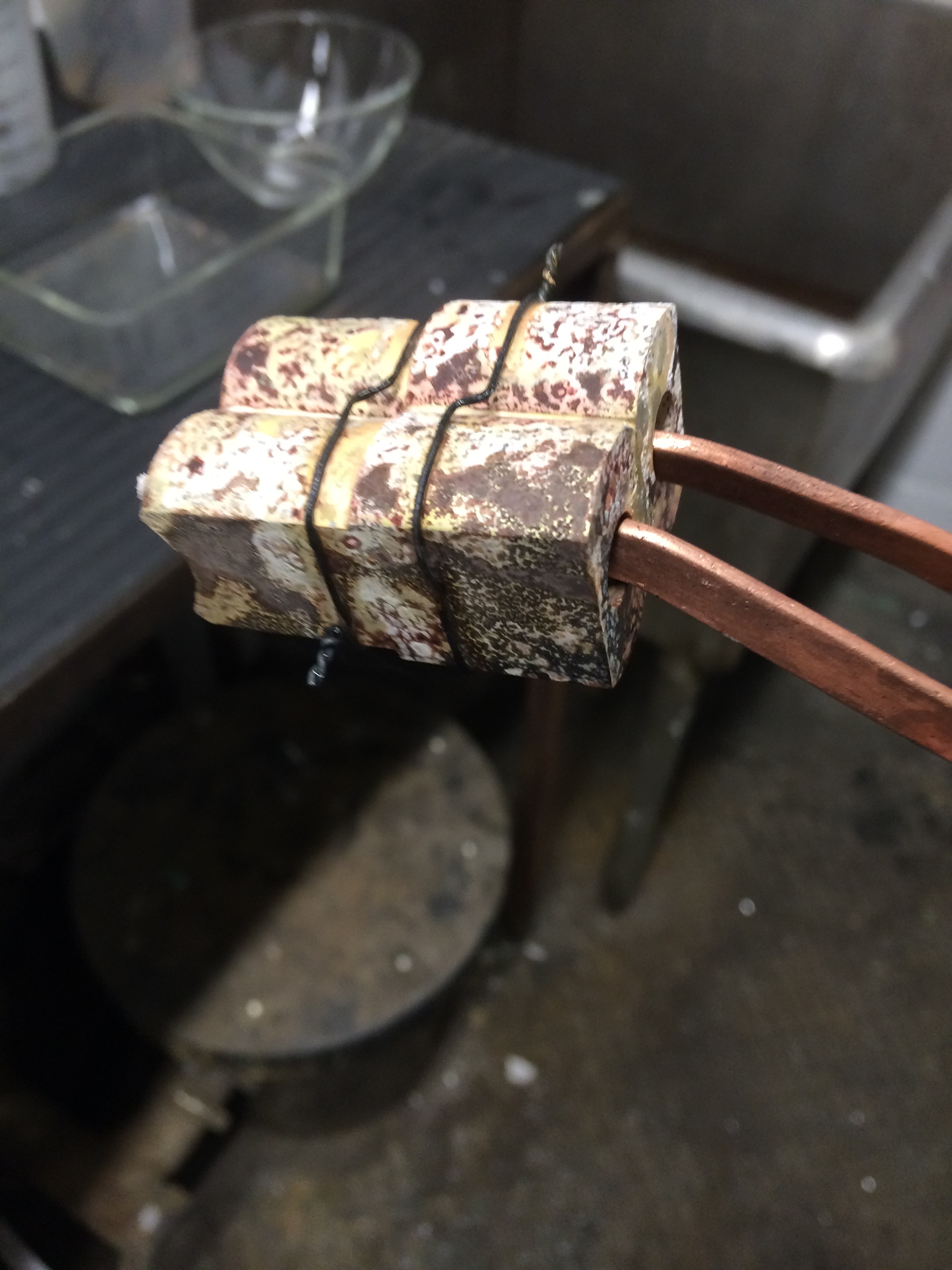


So I've changed up my approach: I have simplified the brass holders for the Tubes.
I have decided to make a mold and cast clear resin enclosure - so I modeled the enclosure, both inside dimensions and outside.
I then CNC routed the forms out of MDF.
Layered the forms and built a box to hold the silicone.
These are the opposite of the forms they will be in the mother mold, meaning the cavity will form a positive and the positive will form a negative.

*note* these tubes burned out with a fair amount of consistency. I believe I have overdriven them, and/or improperly driven the filament. I did not apply an AC voltage to the filament. I am taking this project as a learning one, and implementing this to the Russian VFD tri-color display: https://hannahmishin.com/blog/2015/7/18/vfd-display-clock