Blink
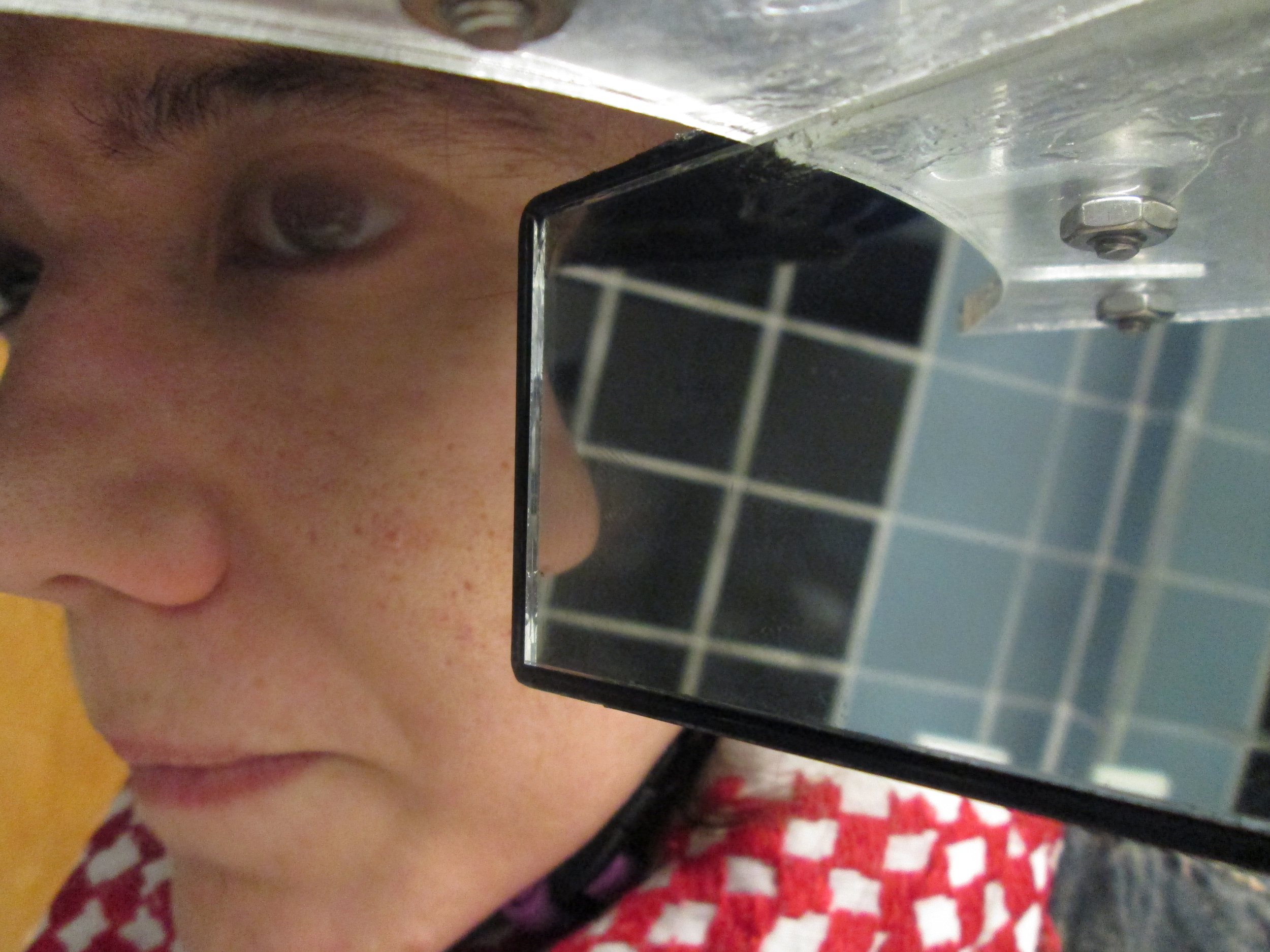
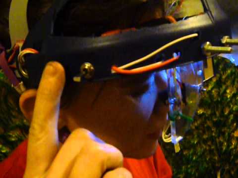
I built a camera rig to fit on the side of my face, aimed at my eye. On this rig is a mirror angled to reflect the world I see. The single video image will capture both my eye and the world around me. I will wear this device for all waking hours for one week. I have purchased and experimented with several small cameras but what gets lost in the scaling down of video cameras are essential components in many ways. I believe the small point-and-shoot one I have at home will suffice. Though it will be heavy its use-ability and reliability counter offset the weight and size. As I need as accurate of data as possible, I require reliable footage and to be able to charge and shoot simultaneously. I purchased a 3M face shield to mount the camera and mirror. The front piece of protective glass was removed (the blue section will remain in place to aid the cameras’ supportive structures.. The camera is mounted at an angle (slightly) so that the eye of the lens sees only my eye socket and the mounted mirror (reflecting the world in front of me). Here’s an image of the shield and camera :


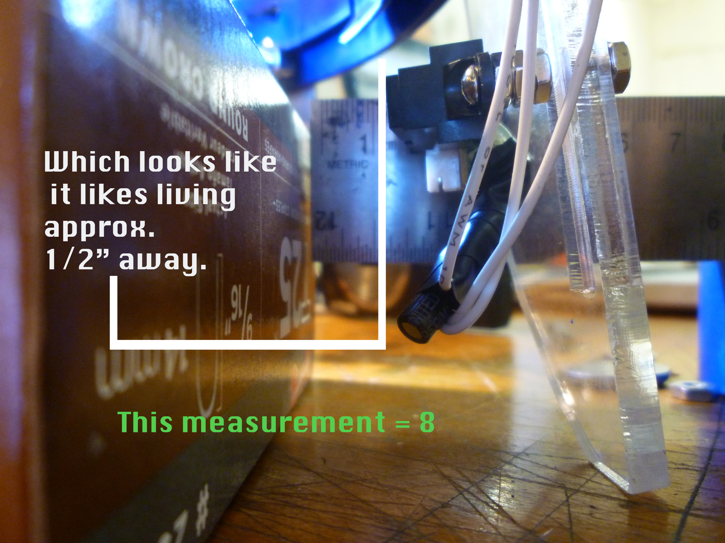
Here is a mock up of the design:

These measurements are precise for my face.

I affixed all components to the helmet. I had some issues with having Processing brightness track, as the light was not only muted due to the overhanging helmet structure (the blue part). Here’s an image of the camera’s capture:
This is a screen shot of the processing sketch with footage. The blinks registered are false, as the brightness tracking isn’t effective. This image is to visualize the sort of display intended:

The image in the mirror registers (saves) a not full opacity still image when a blink is registered (only for the dimensions of the mirror) and represents it (superimposes on top of) the moving image. I then added an LED to see if I could get the “glint” back to my pupil. (to track the glint in processing) This proved ineffective as then, my eyelid became “shiny” or my cheekbone. So much so that the brightness tracker within Processing recorded those as OPEN despite my lid shutting. I modified the original design to help facilitate light and I cut massive holes int he blue part of the helmet. The rig retained its structure but I lost the shadow creating visor. This too, however did not function. As the helmet still has significant structure just above my eye, and will not allow the program to function in low light situations. Then modified the light source and added a headlamp, hoping that the diffused light would still emit enough to “glint” my eye and yet not be strong enough to pick-up the grease off of my eyelid (for instance).


SO…. it still issues that same problem of reliable light source, and when given one, the light is so bright that the reflection on my skin registers white, just like the gleam in my eye. Perhaps then I will add some sensors (or a really excellent one) to know and serially communicate with Processing when a blink is registered. I am thinking of a Piezo as vibration sensor.

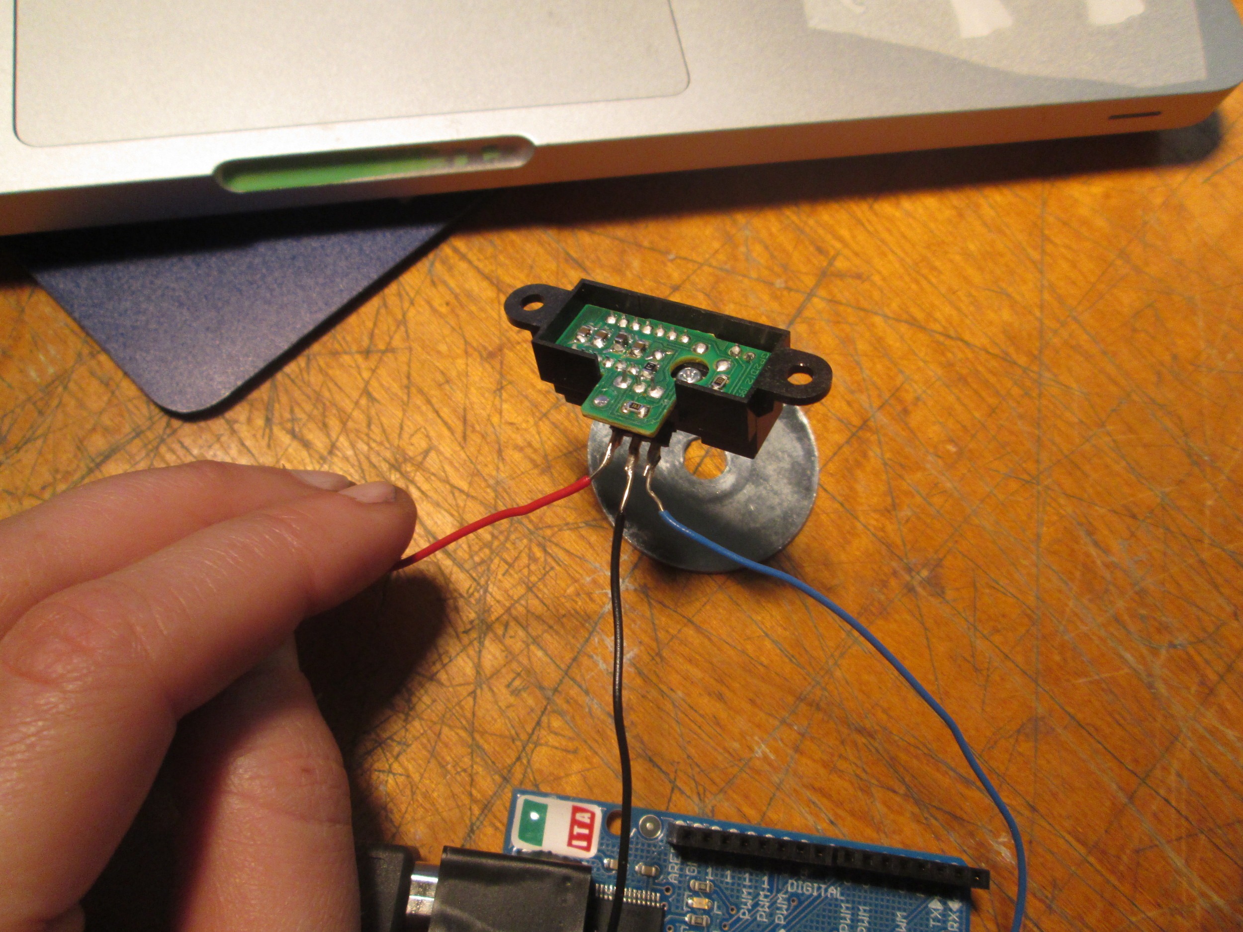
But I think it is both too sensitive and unreliable to function in the way that I intended (i.e. registering muscle movements of the eye), as I plan to eat and drink and walk around. So, I got to thinking about infrared. I have a sensor from another project which I never got around to. https://www.sparkfun.com/products/8959 I soldered the leads:


The values on the top image ranged from 240-248. The values on the bottom image stayed at a constant 255. When I tried this on my boyfriend’s eye, by just holding the sensor to his face there were consistent readings which varied in ranges of 10 according to the state of his eye (open or closed). So for instance when his eye was open I got values (say) from 109 to 117. When he closed his eye it ranged from 120- 124. So, it is a very precise measurement (as I assumed it would have to be). So I planned out how this will function both in code and in the schematic.

So everyone is happily reading values. ButtonPressed is making LED HIGH. Infrared device is giving consistent results.

So, I made the code and got it working on the breadboard.
//these values control the pins and components
int ledPin = 2;
// pin that the LED is attached to
int InfraredValue;
//value from Infrared Sensor
int calibrationButton= 6;
// the button that says. calibrate the distance…NOW
int calibrationButtonState;
//set the calibration state to 0 at beginning
int ButtonPin= 4;
//the buttonPin which controls when to go into calibration mode
//these ints are for controling calibration
int Threshold=0;
// When to have ledPin HIGH or LOW
int TempThreshold =0;
//int to hold the value of the IR sensor when in calibration mode
int CalibrationMode=0;
//when button pressed 3 times w.in 30 secs, CM =1
///these ints are to control the 2nd attempt at millis control
int ButtonPress;
int pressStart;
int waitTime = 3000;
unsigned long time;
// use button press calibration to tell IR to take a reading.
//This IR will register eye CLOSED and make the threshold that reading.
void setup() {
Serial.begin(9600); // initialize serial communications at 9600 bps:
pinMode(ledPin, OUTPUT);//// declare the led pin as an output:
pinMode (ButtonPin, INPUT); //declare ButtonState as Dig.INPUT
pinMode (calibrationButton, INPUT);
//decalre calibration button as inout
}
void loop()
{
InfraredValue = analogRead(A2); //set the IR sensor to pin2
if (digitalRead (calibrationButton)== HIGH){
//set the calibration button state as ON
calibrationButtonState = 1;
}
if (digitalRead(calibrationButton)== LOW){
//set the calibration button state as OFF
calibrationButtonState = 0;
}
//Serial.println(“CBS:”);
//Serial.println ( calibrationButtonState);
if (digitalRead(ButtonPin) == HIGH && ButtonPress != true){
//initiate button counting with time
ButtonPress = true;
pressStart = millis();
}
else {
ButtonPress = false;
//sets the state for the off position
}
if (ButtonPress==true && (millis() – pressStart) > waitTime ){
CalibrationMode=1;
Serial.println (“Calibration mode”);
}
if (CalibrationMode==1 && calibrationButtonState==1){
//if in calibration mode and calibrationbutton is ON, set the threshold to the Infrared value (i.e. ping my eeye an dmesure the distance) //
IR Sensor = threshold
TempThreshold = InfraredValue;
/// Serial.println(“CALIBRATING”);
//BLINK THE LED TO LET ME KNOW I AM IN CALIRATION MODE
digitalWrite(ledPin, HIGH);
digitalWrite(ledPin, LOW);
digitalWrite(ledPin, HIGH);
digitalWrite(ledPin, LOW);
digitalWrite(ledPin, HIGH);
digitalWrite(ledPin, LOW);
}
if(ButtonPress==true && (millis() – pressStart) > waitTime ){
// exit Calibration mode CalibrationMode=0;
//BY FLIPPING SWITCH, THE IR SENSOR RETURNS TO GAUAGING WHETHER OR NOT I BLINK
}
}
// Threshold = TempThreshold;
//CalibrationMode 0 //
in this code i will decipher what a blink is, tell the led to go HIGH //this CODE now
if (Threshold >= InfraredValue){
digitalWrite (ledPin, HIGH); Serial.println(“BLINK”);
}
else{
digitalWrite (ledPin, LOW);
}
// Serial.println (“button count:”);
// Serial.println (ButtonCount);
Serial.print (“IRValue: “);
Serial.println (InfraredValue);
// Serial.print (” tempThreshold: “);
// Serial.print(TempThreshold);
// Serial.print (” Threshold: “);
// Serial.println (Threshold);
}
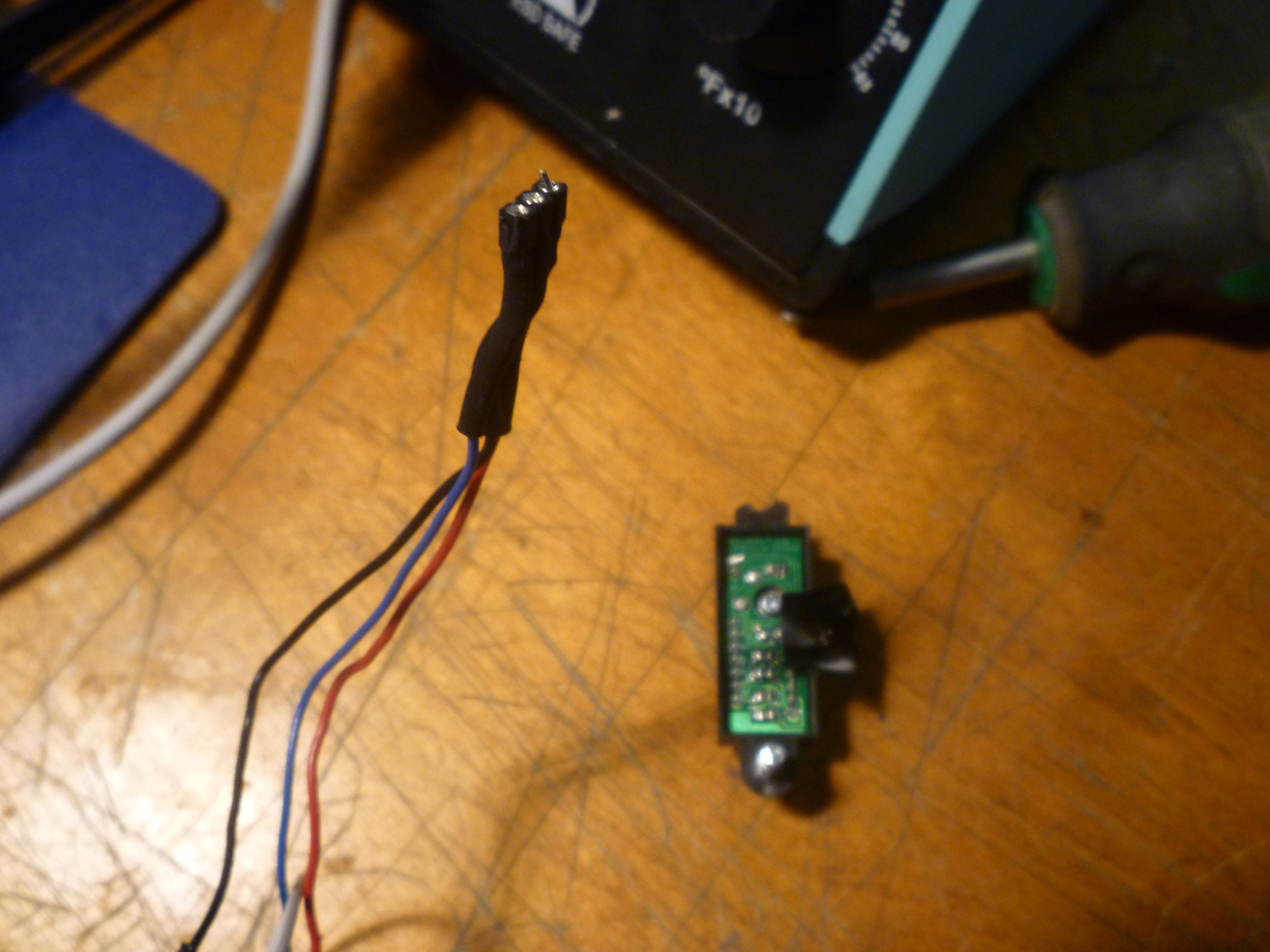
That up there is the code: Here is an image of my attempting to glean readings/reliability of the IR once mounted.

I made a mount for the Infrared Sensor. This took forever. Finally got it going, and could not understand why my readings were inconsistent, as when they were on the breadboard the sensor worked perfectly. I took a look at the back, and because the sensor suffered some —shall we say– ups and downs, the pins loosened. I realized this and re-soldered them onto the board. However, the board does not have copper (or otherwise metallic) rings around the pins, the solder ended up only securing the wires in place, and precariously so. So I taped them down with electrical tape, and still strange readings. So I unplugged the sensor and accidentally plugged them in backwards (as the data sheet for this sensor is ridiculous) and I think I might have “killed” my dear sensor. then my boyfriend came home and showed me a get-around shitty perf-board
However, when breadboarded, the sensor understood distances, though not in the succinct manner as at the first. This gave me hope.
I cancelled my rush order from Sparkfun and tried again with mapping the values. Before this guy got banged around, he read the difference with abundant stability the difference in the table and a table with a 1mm thick object. Perhaps it was damaged, or perhaps the concave nature of an eye socket, or the fact that it is flesh, that the readings remain unstable.

I acquired a slightly different sensor (http://www.sharpsma.com/webfm_send/1208), same make, manufacturer, different model. This guy likes to take readings about 10 -80 cm from the object to be sensed (further distance than the initial IR).
According to the data sheet, I added a 10μF between PWR and GRND. It also gave reliable readings off the breadboard. Whew!
I hooked it up to the rig on my helmet:


I tried varying placement on the helmet, to assure that the distance, placement, orientation etc, are all optimal.
Note the various screw holes:

Placed it just so, so that the values would be collected within ranges the sensor likes and made sure that I was staring down the IR (red and glowing, just like Terminator 2):

And of course, stable readings, but too much variation to read the difference in distance from eyeball to eyelid.
(*as a side note- wow that infrared wears the eye out!)
Here’s are images of the full thing, currently all buttons, IR and LED are inserted but running through breadboard:


So, I test ran the “smooth” code in the arduino site: http://www.arduino.cc/en/Tutorial/Smoothing
These are the readings with the Smooth code inserted:

These values remained unusable, as I could not differentiate a value for OPEN || CLOSED. I noticed that this sensor seems to take readings clearly when placed in a new environment. Before the sensor is “acclimated” to its new measurement, it reads things somewhat more clearly. Once it has been situated it seems less sensitive to change. Perhaps I am personifying the sensor, but this seems to be the case.
I altered the code to reflect a smaller “average” (cycle through an array of not 10 but 2). This still posed inherent problems, perhaps workable?
I tried two IR sensors (whose variations only included the “sweet-spot” range of sensing). I made sure to attempt to orient the sensor in both horizontal and vertical positions:

I went searching for insight and went to ITP’s Sensor Wiki-
In this wiki was the sensor I am working with. I was familiar with most description in the wiki, however, in it was linked Crys Moore’s blog, wherein she broke down some calibration math:
http://itp.nyu.edu/~cm2878/crysmoore/?p=518
I deleted the “smooth” code from my sketch and inserted this math instead:
distance = (2914 / (Infrared2 + 5)) – 1;
here’s a video of the results:

and here is my 1st attempt at calibrating spacing:
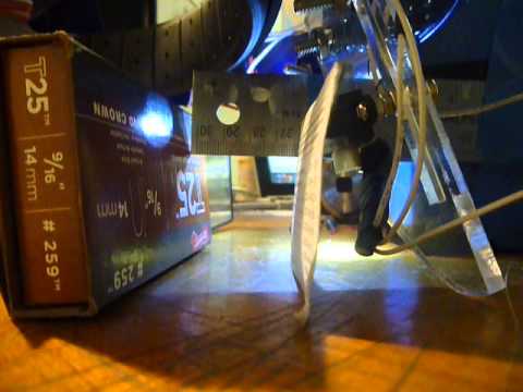
So it works.


A video explaining functionality:
Processing does NOT like High resolution .mov files. Instead, I cut the footage (for processing) into 3 minute sets and put these individually into processing. I then told processing to save an image each time it registered brightness in the upper left hand corner of the .mov file (when I blink).
I then saved these images (below are some example "blinks"):


The footage above was sent in sections to a processing sketch which I saved all blinks, and then put these blinks (30 minutes) in a poster:
