Amplifier Amplifier Amplifier
For the POISED project, I have a bi-polar signal from a PMT with a DC offset (voltages range from approx -2 to + 0.75). I need to translate this signal to be 0 to +5 volts.
This blog post contains information specific to the problem stated above. For information on the project, please see THIS blog post
For the project, I will need an amplifier which functions in the lower Mega Hertz range. My first research task was to identify Video Amplifiers and discern amongst those, which were for augmenting or altering standard signals and selecting those which were not configured for specific application (i.e. camera phones or CMOS etc.)
The signal from the PMT is not stable and has very little current. As such, I only require video speed, no other video specific attributes.
Here are some Amplifier Primers:
And a Texas Instrument write up of video applications with amplifiers.
Here is a nice write up of how to single supply a bipolar amp.

Signal from PMT - bipolar
Impedance
The first issue I came across was one with impedance mismatching.
I configured several amplifiers, using a function generator. When using the output signal from my PMT, the PMT signal would be completely nullified.
Impedance is kind of like resistance, but is more complicated. See the link below for the best explanation I have come across defining electrical impedance:
I tested the output impedance with a variable resistor box like the one above. The resistor value which allowed the PMT signal to not be nullified attenuated that signal (i.e. the resistor reduced the signal strength). Therefore I began configuring a buffer amplifier to feed the signal through.
Amplifier ICs can be configured in a variety of ways, the buffer amplifier configuration is one with unity gain. An article from wikipedia states:
A voltage buffer amplifier is used to transfer a voltage from a first circuit, having a high output impedance level, to a second circuit with a low input impedance level. The interposed buffer amplifier prevents the second circuit from loading the first circuit unacceptably and interfering with its desired operation. In the ideal voltage buffer in the diagram, the input resistance is infinite, the output resistance zero (output impedance of an ideal voltage source is zero). Other properties of the ideal buffer are: perfect linearity, regardless of signal amplitudes; and instant output response, regardless of the speed of the input signal.
Buffer Configuration
I sourced a video buffer amplifier - BUF602 Amplifier from Texas Instruments.
I took the schematic from Fig 31.

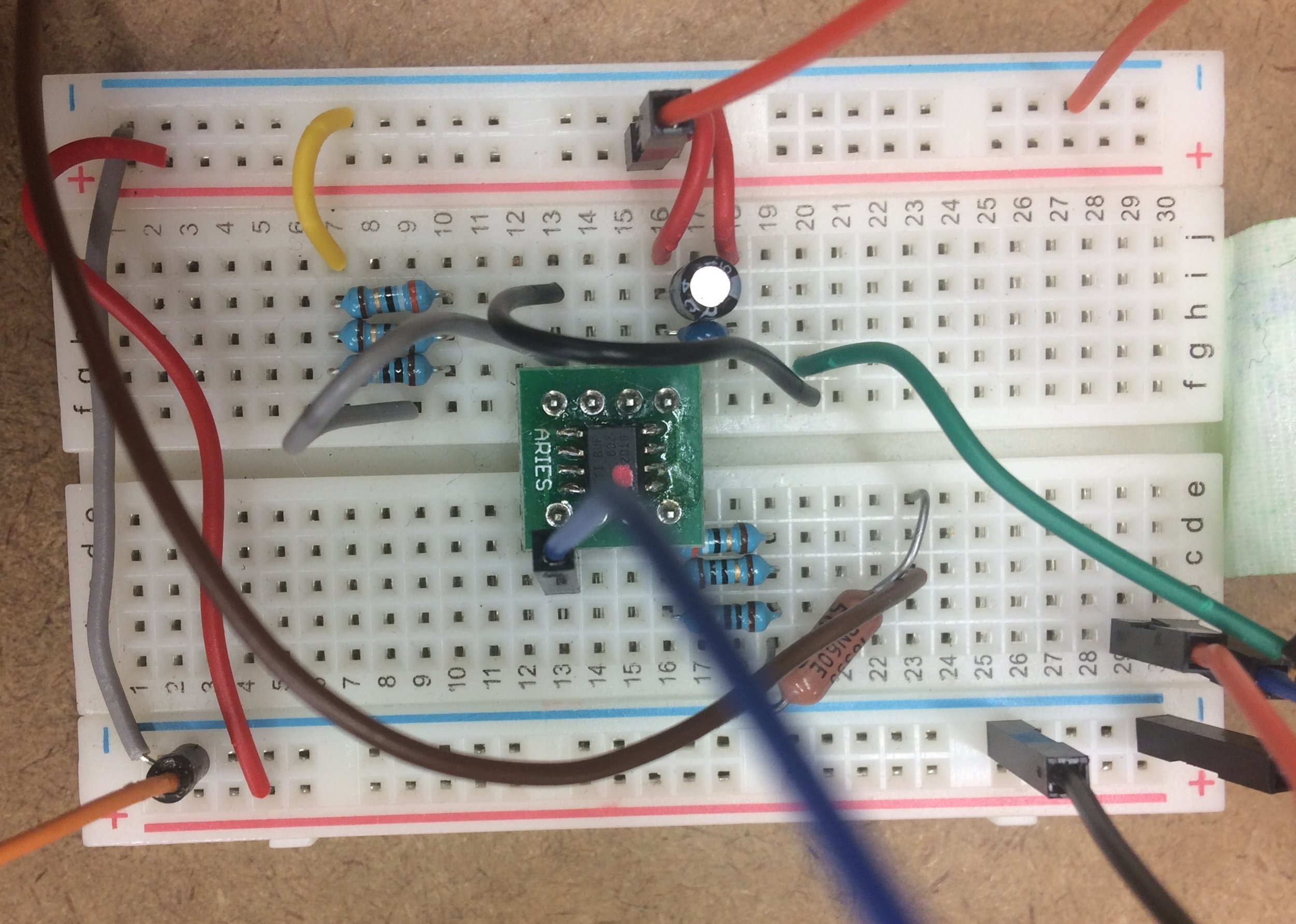

BUF602 Scope Reading
So now that I have the PMT going through a buffer, I need to contend with the voltage offset and the bipolar waveforms.
Full Wave Rectifier

Full wave rectifier
The full wave rectifier takes the negative voltage and makes it positive.
____________

Click the image for the org. site
So I made the above circuit using the MCP602 Dual Op-Amp (using vanilla op-amps to configure properly before troubleshooting faster OpAmps).
The signal is attenuated and the values are no longer negative.

Yellow is Rectifier Signal - Blue is PMT out.
I changed the chip out to a L272 dual op-amp.

No signal attenuation with the L272 Op-Amp
The L272 does not attenuate the PMT signal. The incoming signal is positive.
However, this IC creates a negative 4 DC offset. Meaning that, in relation to ground, the signal operates at negative 4 volts.
Removing Voltage Offset
By using capacitors - carefully selecting those- will move the voltage level.
I configured several capacitors in series and successfully moved the Signal Line from ~negative 4 volts to +/- 200mV.

Yellow is Coming off the rectifier circuit, blue is that same signal but with caps in series.

I got my DC to ride at 0VDC using a series of capacitors.

0vdc after capacitors
However, despite having rectified the signal, I still have some information in the negative.

some information remains un-useable as it is in the negative.
There is a way to add voltage as a Summing Amplifier configuration.
- The addition of voltage needs to come in at the input of the amp and match that impedance.

Buffer voltage out

rectifier voltage out
I plugged ~2.5 volts into the Positive input of the second of the two dual op-amps.

This added voltage brought the signal to ~+1.5 volts.

Blue is the +1.5 volt signal after adding voltage on Pin6 of the L272 IC
I configured the voltage divider to provide 2.23 volts to the positive input of the L272 IC.
This brought the voltage offset to ~+.75 volts. This is enough above ground to not have any data lost from the PMT signal.
This circuit functions - please see the Eagle Files HERE


Video Bandwidth
So now that I have a circuit configured with a fairly vanilla op-amp, I need to take this schematic and use a video-speed amplifier. The L272 operates at 350Khz.
A video amp should be in the Mhz range.
Some common design issues when working with high speed amplifiers are constraints of wires and tightness of the circuit (physically)- contending with EMI.
I emailed Fairchild, the manufacturer of the L272 IC requesting a faster amplifier with the same characteristics.
They wrote me back within 24 hours! Go Fairchild!
Here is the IC they recommended:
Parasitic Oscillation
https://e2e.ti.com/blogs_/archives/b/thesignal/archive/2012/05/30/taming-the-oscillating-op-amp
https://cds.linear.com/docs/en/application-note/an148fa.pdf
http://analogmodules.com/oscillation-in-amplifiers/
________
Power amp vs. Voltage amp
power
https://media.digikey.com/pdf/Data%20Sheets/Rohm%20PDFs/ba4560[1].pdf