Laser Scanner- camera/projector
This is the research and experimentation to create a DIY laser scanner involving two lasers and 3 oscillating mirrors on an optical plane to create two distinct raster scan patterns.
I began thinking about what I would want to make with lasers and galvos (keeping in mind, I plan on making my own psuedo-galvo - likely by jiggling (not "moving") a small stepper motor only on one coil (never switching to the next for rotation).
I wanted to make a camera of sorts, using lasers as both the lens and as the photograph itself.
---in real time?---
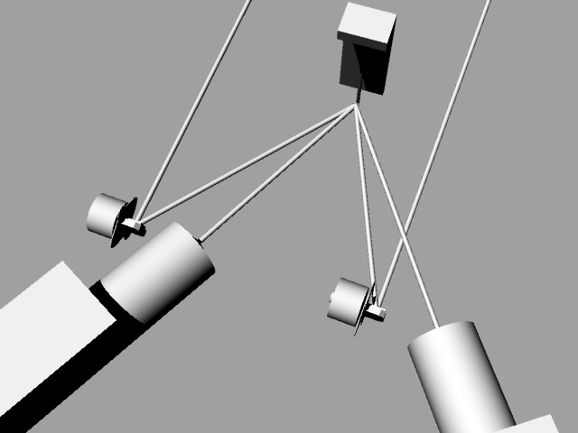
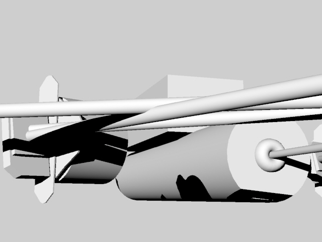
Below is a mock up of the project:

galvanometers :
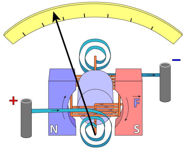
Which is the basic mechanism which creates an old school ammeter indicator. They are used in these "laser light shows" and are the drivers for all professional laser shows because micro-incremental changes create massive changes in the image projected by the laser - they also can move back and forth (tiny but very precise movements) with rapidity. For a laser to seem to draw a seamless line, it is imperative that the actuator has the smallest lag possible.
So in prep for the mechanism I first need to know how to move my lasers' light in sync.
In reading the tutorial on Sequential IC Circuits, I found that I needed to know what kinds of Logic Gates the article mentions: NOT NOR NAND (there are more, and here is a list for reference (http://whatis.techtarget.com/definition/logic-gate-AND-OR-XOR-NOT-NAND-NOR-and-XNOR)
The below images are quick reference to those mentioned in the IC Timer tutorial >>
A logical inverter , sometimes called a NOT gate to differentiate it from other types of electronic inverter devices, has only one input. It reverses the logic state.
The NAND gate operates as an AND gate followed by a NOT gate. It acts in the manner of the logical operation "and" followed by negation. The output is "false" if both inputs are "true." Otherwise, the output is "true."
The NOR gate is a combination OR gate followed by an inverter. Its output is "true" if both inputs are "false." Otherwise, the output is "false."

This tutorial about sequential logic ICs and circuits :
http://www.electronics-tutorials.ws/sequential/seq_3.html
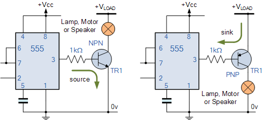
So I am thinking of using a 555 per axis (2 scanners = 2 555s) and a transistor per stepper (4 transistors).
So I had this transistor circuit lying around from thesis troubleshooting.
Now I need to find the right 555 Resistor and Capacitor combos.

Eric Rosenthal set up the circuit to test that the motor would fluctuate:
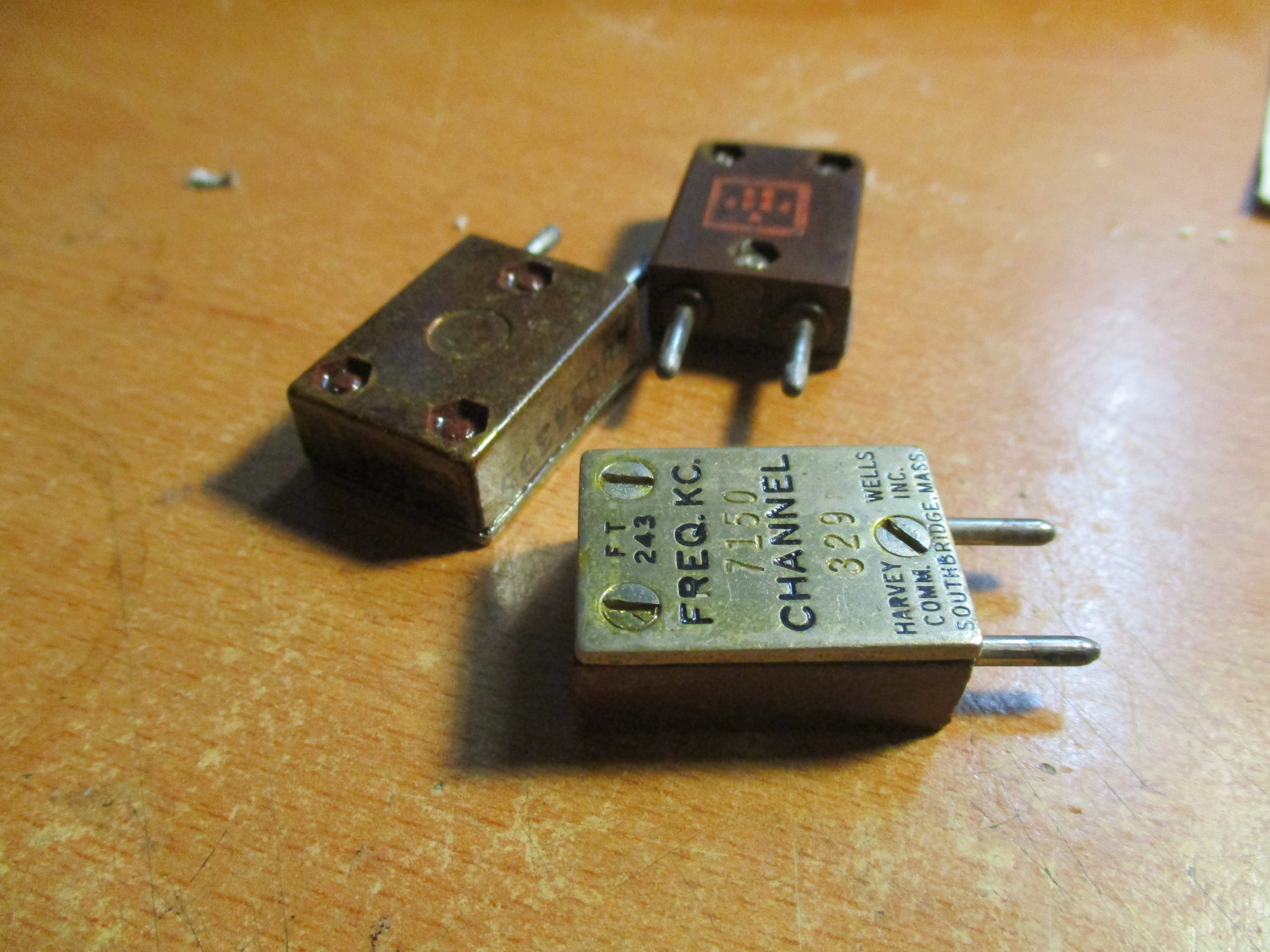
I am tasked with characterizing each stepper I own - as again, I am looking for the maximum range of motion that lives on one coil of the stepper. The ones I purchased for this project:

This motor ("mercury ston35-15-11c") is a 12V . 400mA . 7.5° motor.
I assembled almost all of the steppers I own (with a few specialized exceptions).

I am looking not at power or amperage or torque, but rather at °. If the ° of rotation on one coil the more the more resolution the input and output scanners will have available.
The first test of characterizing each motor (again looking at the degree per coil) is to power the coils directly from two separate power supplies in series.


I need to mount a mirror on the shaft of the motor and point a laser onto the mirror. Then if I can make my laser project onto a flat surface on it with control, then I can use that motor as a galvo (meaning there is resolution there).
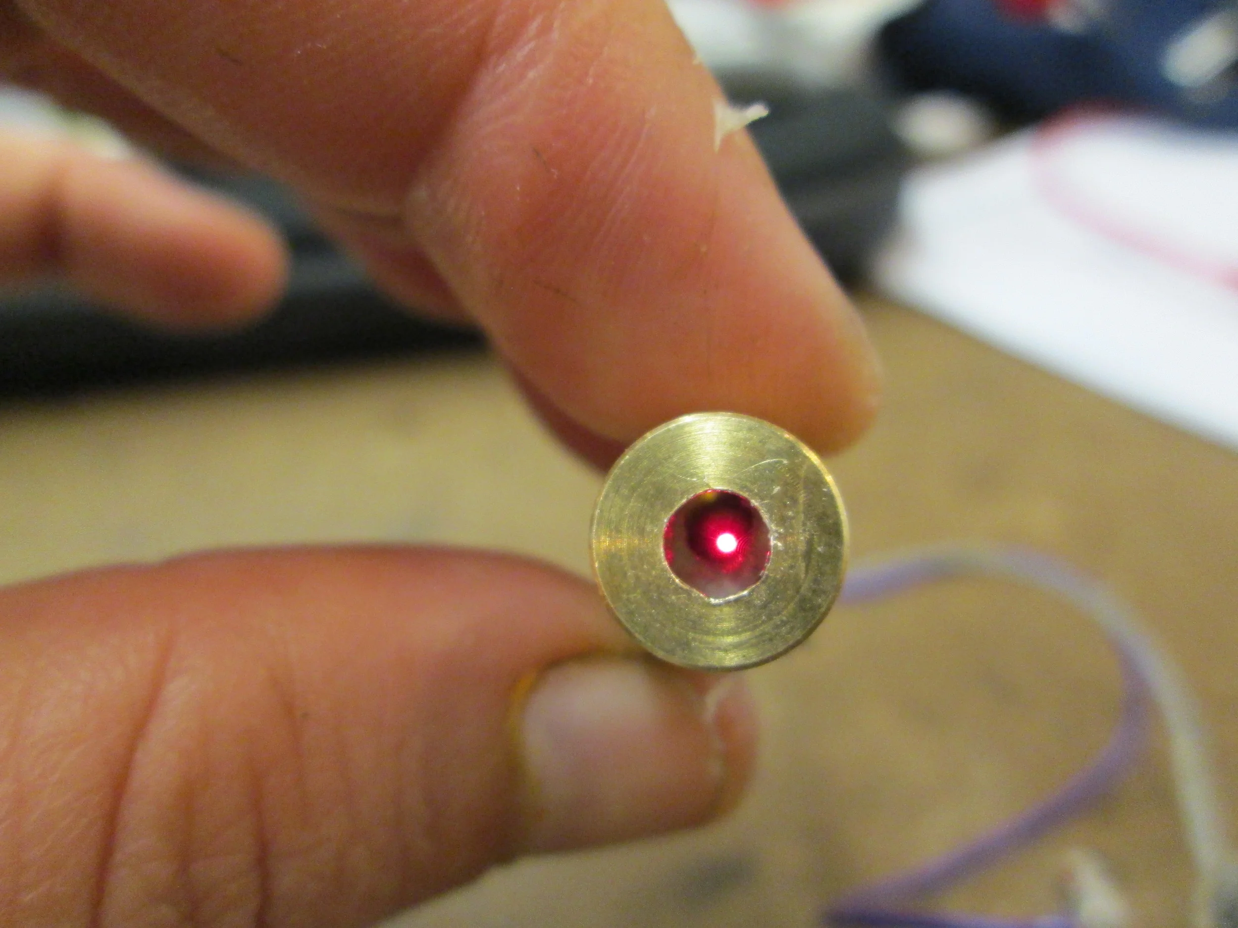
So I split open a cheap-o laser. Low and behold there were mirrors in there ready for mounting (as I destroyed 1.5 by trying to drill into the sides).

So I hacked it to take the laser diode out of the casing and I removed the momentary switch and replaced it with a on/off switch.

Then I prepared the first test of the first test.
Seeing how much movement a tickle of power wiggles one coil, and how it translates to length of motion.... I placed the motors in approx. the same place on the table and the laser on approx the same place... and I measured the distance when projected.

Most of my motors, strangely, were 1.8° rotation. I tested 3 of these, all of which measured at ~ 1 3/8". (WANTAI 57BYGHY20/ DANAHER/ MERCURY SM-Y2BYG011-25).
The WANTAI 42BYGHM809 .9° measured at 3/4".
The Mercury Motor mentioned above (mercury ston35-15-11c) with a 7.5° rotation measured at ~ 2 5/8".
I also looked at how quickly the beam of light jumped from one extreme to the other... if I turned the voltage up on one of the power supplies slowly, how slowly does the laser move to its extreme position?
The motor which seemed most responsive to slowly moving along the coil was the unknown model stepper (the one in the video below).
This small step motor measured at almost ~ 2 5/8" with a stated 3.6° rotation.
I think that the small amount of controllable movement gained from the steppers (meaning, magnetize one side, slowly magnetize the other, and how long does the shaft/mirror slowly move in the direction of the other side...eventually it just - jumps-) isn't enough for the use of steppers - or at least the kind that i have. Eric agreed.
another option for motorization - unexplored:
From the St. Paul MN store called Ax-Man - http://www.ax-man.com/-- four of these CD spindle DC motors. I picked them up randomly many years ago, because I liked the cut of their jib, and for 2 dollars I bought six of them.
They have no shaft and are meant to run at super high speeds (for optics).
They are similar to this model- manufactured by the same company- but vary in specs to some degree:
http://www.nidec.com/en-Global/product/motor/category/A010/B010/P0000011/
Though they may spin fast enough for the resolution of the input and output, they do not rotate back and forth quick enough or reliably the same -enough- to be used for this purpose.. maybe

Of Note: Rosenthal mentioned that Drones have DC motors which run super fast. They are 3 phase DC motors- (http://www.allaboutcircuits.com/vol_2/chpt_13/6.html).
The drones have all driver circuits required, and I found what I think to be a driver for a 3 phase motor: "Neewer® 30A Brushless Speed Controller ESC for RC Multicopter Helicopter Airplane"

These motors are similar to those spindle-less DC motors I mentioned above.
(I never ended up exploring this avenue, but good to remember).
A perhaps, more viable option--
So Eric Rosenthal brought me two laser scanners from the guts of fax machines. A super interesting concept, that this has existed for a long time now:
http://mindmachine.co.uk/products/01_Printer_Gen_Faults_Horizontal_Jitter1.html
The model shown in the article is the one that Eric lent me:

The parts that I want are the polygonal mirror mounted to a motor.
It is attached to a driver board.
The brains of that board is a TA7259P (Data Sheet link): http://audiolabga.com/pdf/TA7259P.pdf

Eric and I sorted out how to circumvent the input signal it would want to have to begin moving.
I ended up drilling out the lens in my cheap-o laser, as it was not focused properly.
This lessened the intensity of the laser, not strengthened.
So Eric lent me a lens to help focus it.
I mounted the laser in a tube and the lens on the other side:

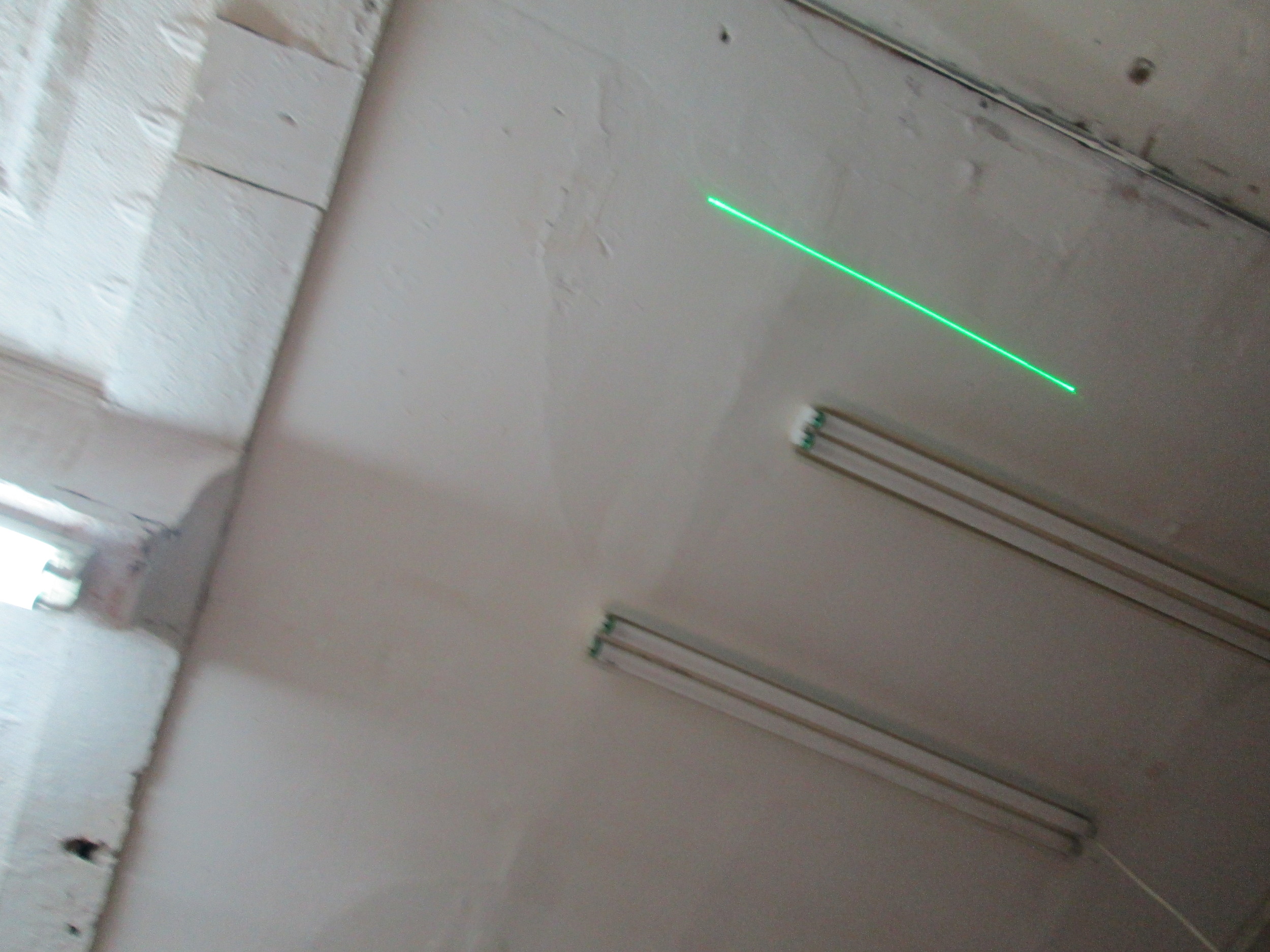
I then attempted to aim the laser to an edge on the mirror and see what I could get:

--- The not - succinct line is the reflection of a not focused laser. ---
So I finally got my green laser (z-bolt) in and began testing it with the polygonal mirror.


I got myself a line! Got a good line, by using the built-in calibration of the unit that the polygonal motor came within.
I noticed that when the laser, pointed through a lens in the casing, at the polygonal mirror, it produced - not a dot- but a line:

Obviously, difficult to photograph - the above = a line - not reflected- but projected from a laser which should normally look like this:
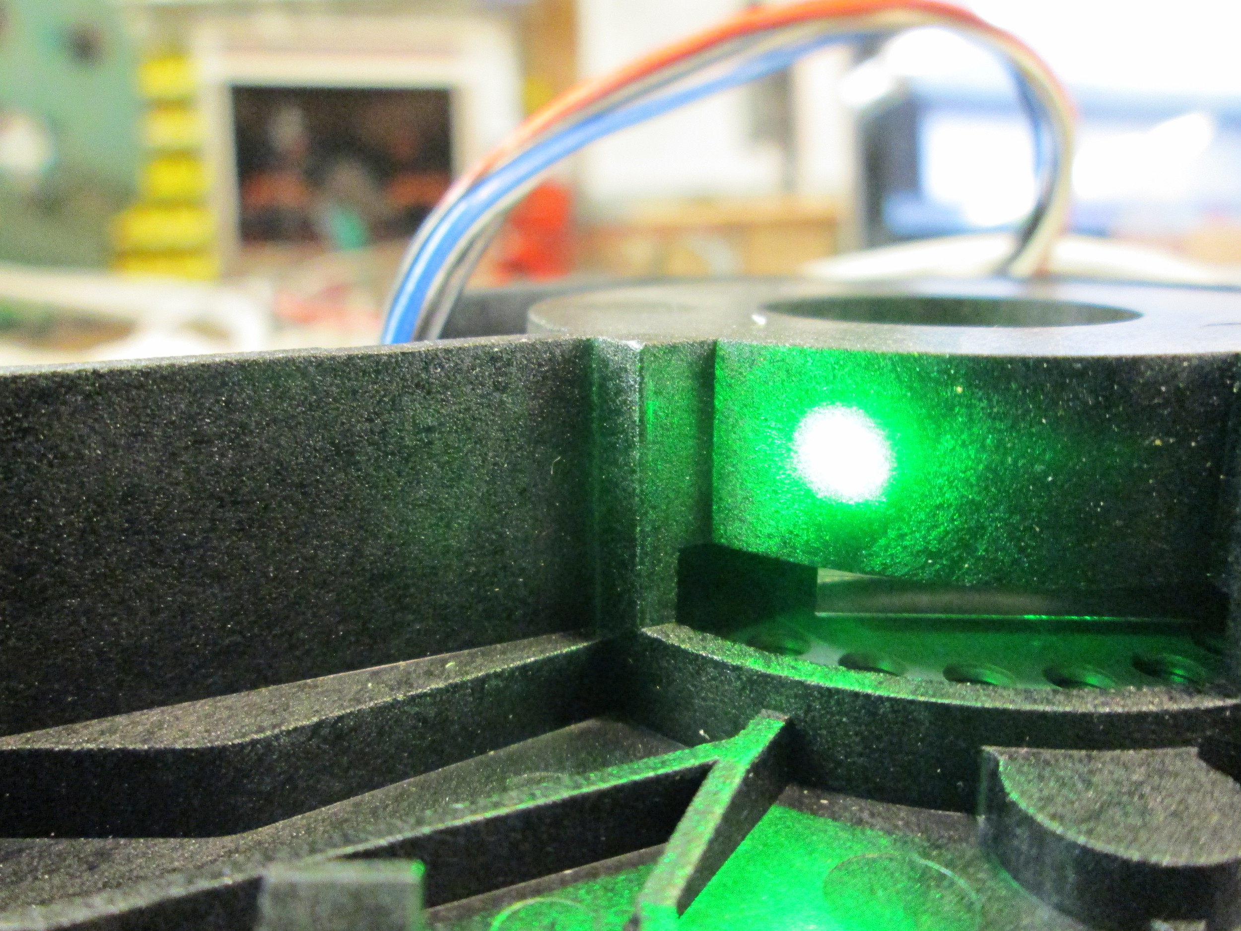

That being said- the polygon scanner only generates a line at approx. 60Hrtz.
Hertz = cycles per second. RPM = rotations per minute. Because this resolution of the scan and image is dependent upon resolution, the more HRTZ achieved, the higher resolution the project will be.
The galvo - laser scanner setups generate a singular line, I need many many of those lines. Therefore Eric Rosenthal and I are exploring a myriad of methods for causing an almost weightless highly reflective object to vibrate - linearly -
We tried a piezo, which did not vibrate with the optimal Hrtz -
So I am trying a speaker.
Tweeters (https://en.wikipedia.org/wiki/Tweeter) to be exact, as they are constructed to produced sounds at a range of 2K Hrtz - 20K Hrtz--- (these measurements are also measured in HRTZ - the oscillation of the sine wave - its peak -to- peak time - -- sound is a linear wave of pressure---)---
I have tried many variations of this tweeter oscillation-The highest frequency range I achieved prior to these photographed here - was 1.2K
Here are some of my attempts:

So, in my research on trying to fabricate an almost no mass mirror at such high frequencies requires a very precise mounting (as glue only adds mass for instance).
However, most tweeters (ordinary ones) cap their frequency range at 15K, and if Pcomp has taught me anything, it is that you do not want a part that caps at the desired x for your project (replace x with amps or hertz or rpm or torque), you always want a part that is capped as much above what you are after as possible.
I did some research, and higher end tweeters are available which cap at faster Hertz.
That being said:
I am giving up on the tweeter, though it has brought me the closest to my desired Hz yet, it can never be done so to move the laser beam precise enough to be successful for my purposes.
Why so high and precise Hertz?
The reason that 15K Hz. is such a desired frequency, is that this is the resolution of the scan and projector. This math begins with the NTSC hz. range (https://en.wikipedia.org/wiki/NTSC).
That == 15.750 hz
divided by the frame rate:
30 FPS
which tells me how many lines I get in each frame
535 lines
so that == 535 lines from the first line to the last line per frame.
I did an internet search: "vibrating reflective surface at 15K hz" and the first thing I found was this site:
http://www.eopc.com/sc30.html
It turns out their shop is less than a mile from my studio!
I spoke with the owners about this unit and they are working with me on a payment plan for this model:

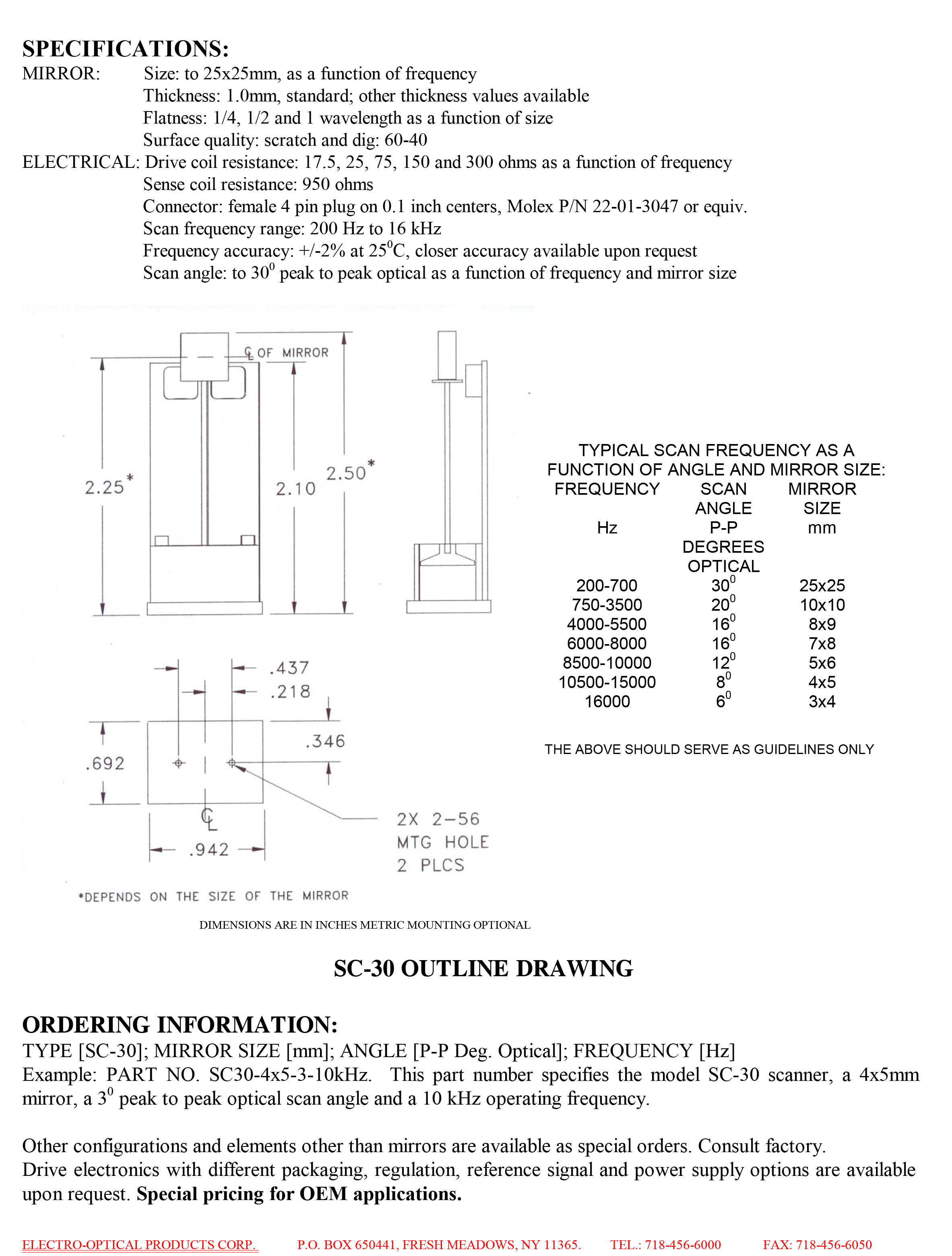
They were ever so kind, as the owner sat with me for over an hour discussing the ins and outs of optics and laser scanner specifics.
They are amazing!
This optical scanner will directly receive both inout and output laser beams. This unit will create horizontal lines to be projected onto two distinct actuators for the vertical... aiming at with either 30 or 60 Hrtz, in keeping with the aforementioned NTSC frame rate.


This circuit requires +12 and-12v. So just to check my logic on how to make two power supplies provide positive and negative voltage, I found this tutorial:
https://electronics.stackexchange.com/questions/78962/positive-and-negative-potential-via-two-power-supplies-with-common-ground

speaking of lasers-
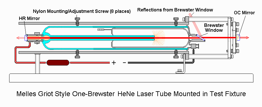
I am getting two HeNe *Helium Neon* lasers from this supplier:
http://boomerssupply.net/shopexd.asp?id=261

this is what it will look like....

(OMFG)
Here is how it works:
I mean look at this:

Anyway- sexy lasers aside- there is a point to using these, as they are not made and do not function as a laser diode assembly does-
LASER stands for Light Amplification by Stimulated Emission of Radiation
Here is a SIMPLE explanation of LASERS - aptly named lasers for dummies:
http://www.wickedlasers.com/laser-tech/dummies.html
It is a means of keeping the light emitted within a tiny focal range over long distances.
In typical laser assemblies, it is a laser diode (https://en.wikipedia.org/wiki/Laser_diode) - basically electrons fight with gaps and when they do, they produce photons - optical amplifiers and/or mirrors assist in strengthening the laser's output.
LASERs suffer from deffraction over time- meaning - the "beam diverges (expands) rapidly after leaving the chip, typically at 30 degrees vertically by 10 degrees laterally"- lenses are used to refocus the beam.
In the case of gas lasers- and the HeNe- Helium and Neon collide to produce light.
And from this wikipedia- === https://en.wikipedia.org/wiki/Helium%E2%80%93neon_laser
How a laser diode works, is from blob of light - focused by use of a lens. - Meaning, if the focus distance is not paired with the focal setting of the lens, the beam will be unfocused.
He-Ne functions by producing a singular wave. Meaning they are born as a focused point, and only falter from that focused wave when it encounters gaseous particles in the air.. so there is loss, but, in comparison, the He-Ne is the superior unit.
Because of the mostly lossless light emitted by Gas LASERs, accuracy of image will come - in part- from the density of the laser light.
Either way- this laser is a Class 2 Low Power Visible Laser (http://web.princeton.edu/sites/ehs/laserguide/sec3.htm#class2)
Lasers can produce light across the spectrum. When trying to find a laser to suit a particular application (color or whatever) Here is a guide of what lasers produce what spectrum of light.
So for instance an Infrared laser is usually slated as 700-1400nm. (nanometers- how the spectrum of light wavelengths is measured.)

Because I am using silicone as a photographic element- Silicon photonics is the study of silicone as an optical medium:
https://en.wikipedia.org/wiki/Silicon_photonics
Silicone really likes Infrared. My application requires visible laser light on the input/camera scan: Therefore the closer I get to Infrared - the happier the silicone is on reading the reflections.
There are four basic requirements for this project to be a success:
One is mentioned above- the density of light being reflected/projected
Two - is the synchronization of the x and y axis of both the input (camera) and output (projector) mirrors
Three - is the speed of those mirrors
and
Four - is the sensitivity (the larger the variable feedback numbers avail) of the photocell.
I now have real galvos!

In researching Galvos, when shopping for the the HeNe laser, there, from the same supplier- were psuedo-galvos made from stepper motors. (http://boomerssupply.com/galvo/)
This is the schematic they provided which drives the stepper with a pot:

To find the coil pairings one measures resistance across the leads, just the same as one would to find the coils pairings on a stepper, for instance.
In my case - the coils (4 total wires, 2 wires per coil) are beside each other.
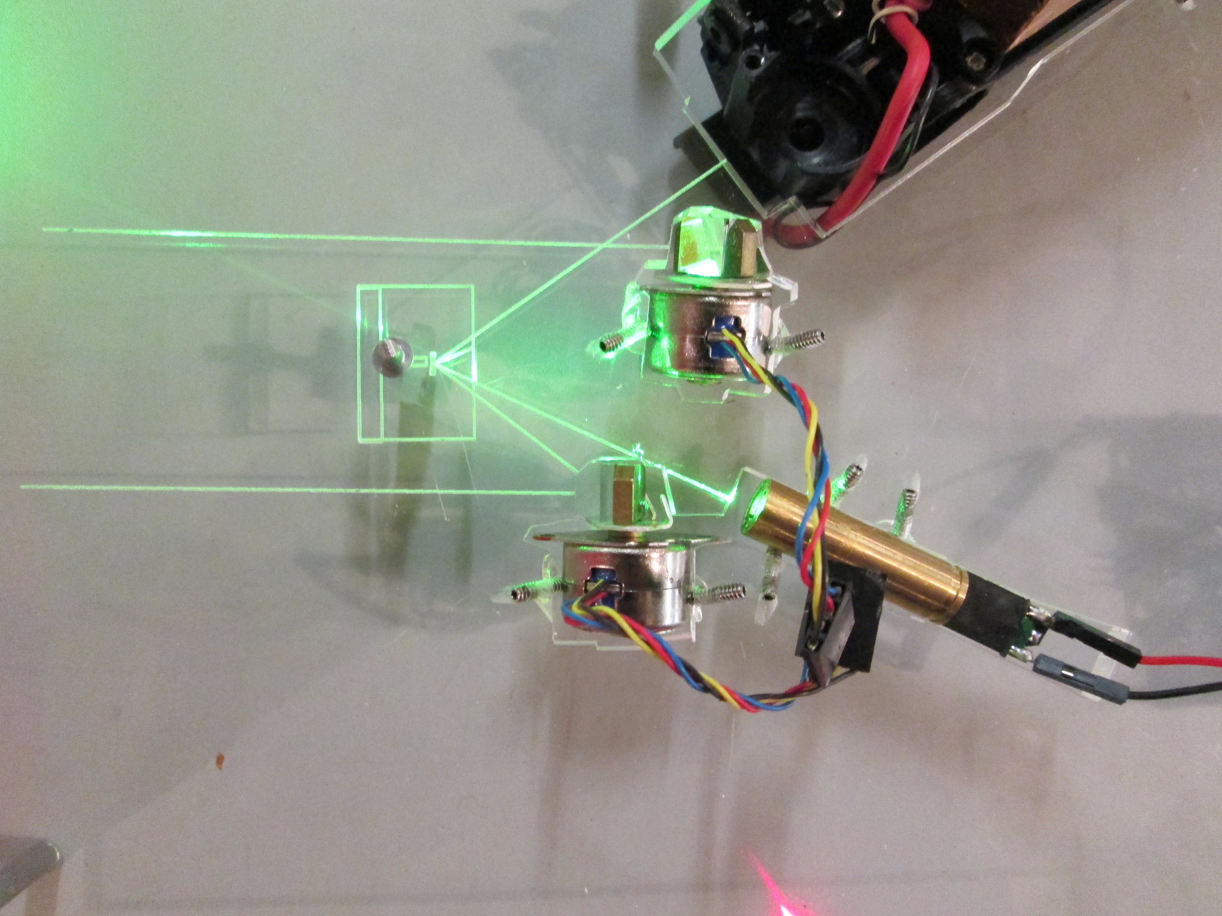
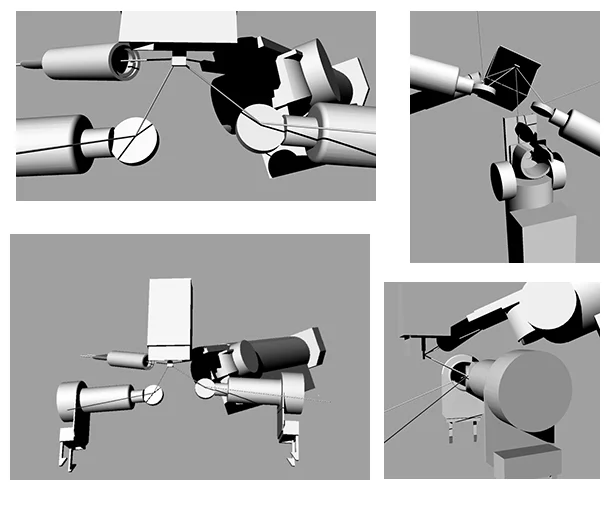
FABRICATION OF THE OPTICAL FIELD:
This fabrication technique will be more complex, because I am building a precise jig to hold a beam of light and send that light where I want it.

The laser beams do cross one another, but this is of no concern.
The closer the lasers can be to the oscillating mirrors the larger the raster scan areas will be.


So I began working on sussing out and confirming the layout for laser cutting acrylic.
I cut these contours/profiles out and mounted each object with set screws (so that I can adjust placement).


This is a video of my manually manipulating the galvos in the prototype. Note, the angle comes from the not level lasers and galvos. The laser diode (green laser) is catching some of the plexiglass on its journey from laser- to mirror- to wall.
There were a few issues with the above prototype of the optical field.
The main one being that the set screws did not really hold the objects in place. In addition, I felt placing the HeNe in a secure housing/ as in its current state it was difficult to mount.

Seems that the lasers are on the galvos (not centered- as tolerances do not allow).

I was surprised at how much dissapation happens on the laser diode (compared) to the HeNe, I had to tilt the galvo out of line with the HeNe to even see it reflected at all (the red). I photographed it because it was pretty.

While I wait on the High Frequency Optical Scanner from EOPC (http://www.eopc.com/sc30.html) - I am going to program an arduino to specific PWM frequency for the Galvos.
I need to program the arduino to output 10hz at 50% (i.e. 50% of 255 ).

In looking at how to program the specific Hertz - it requires resetting some low level timers of the arduino.
http://playground.arduino.cc/Code/Timer1
but instead of dealing with micro seconds I decided to merely manually PWM'ed with Millis
If I want 10 hertz - that equals 10 cycles per second- and millis functions with miliseconds- 1,000 miliseconds in a second - so I manipulated the "Blink without Delay" example code where my interval is 50 = in my estimation, that should give me 10hertz at 50% duty cycle... ????
I tested the galvos with said code:
This is the result.
But this is not how galvos should behave. They should not move so violently.

that larger blob in the center of the lines are the mirrors' centers.

Some slight adjustments should correct the angles... to make them match... that's for another day however...
and I was doing it all wrong (above) -- using the tone function in arduino I am able to osc. the galvos as they want and have a nice line --
file:///Applications/Arduino.app/Contents/Resources/Java/reference/Tone.html


I got the optical scanner into the mix and began making rasters.


Some calibrations required to the design. This (below) is a video with the new design. Still some tweaks but prior tweaks have been rectified. My next step is to code the galvos to output the correct amount of vertical step downs.
The galvos are based on code... listening to the frequency of the oscillator and counting those pulses... this will ensure that the osc. and the galvos are synchronized... The bouncing of the raster scans is based on inproper galvo use.
Looking into to how to count high frequency pulses with arduino I cam across a few board postings:
http://forum.arduino.cc/index.php/topic,19671.0.html
http://techosapien.blogspot.com/2010/02/arduino-digital-pulse-counter.html
http://interface.khm.de/index.php/lab/experiments/arduino-frequency-counter-library/
I have an input which pulses at (rounding up- 16k Hz). I need to count the pulses and at 252 pulses (approx 62 times a second), I need to fire a galvo. I need the (galvos) output to be synced with the (oscillator) input - so just doing math isn't going to work for this application.
I have been able to have arduino tell me the frequency of the input and it does so fairly accurately. (lib: frequency counter) This means, the arduino is counting the pulses, however I cannot seem to find the variable which does so... (if (unknownVar == 252)) so that I can send the pin high each time.
I also looked at 18.7 Counting Pulses in the arduino cook book and none of the stated variables in the code below either produce a positive or do so, but at a rate which is not in sync with the input pulses. (arduino cookbook code below)
/*
* HardwareCounting sketch
*
* uses pin 5 on 168/328, pin 47 on Mega
*/
unsigned int count;
unsigned int getCount()
{
TCCR1B= 0 ; // Gate Off / Counter Tn stopped
count = TCNT1;
TCNT1 = 0;
bitSet(TCCR1B ,CS12); // Counter Clock source is external pin
bitSet(TCCR1B ,CS11); // Clock on rising edge
bitSet(TCCR1B ,CS10); // you can clear this bit for falling edge
return count;
}
void setup()
{
Serial.begin(9600);
digitalWrite(5, HIGH);
// hardware counter setup (see ATmega data sheet for details)
TCCR1A=0; // reset timer/counter control register A
getCount(); // this will start the clock
}
void loop()
{
delay(1000);
Serial.println(getCount());
}
so I have decided to provide arduino an exact divisor of 15.77 kHZ. In so doing I get around a lot of issues and am able to still exert precise control.
Here's another code:
int inpin = 7; // connect 15724 square wave to this pin
int outpin = 8; // connect 30 hz output to vertical galvos
double duration;
unsigned int durationNew;
void setup()
{
// Serial.begin(9600);
pinMode(inpin, INPUT);
pinMode(outpin, OUTPUT);
}
void loop()
{
duration = pulseIn(inpin, HIGH);
duration = 469/(duration)*1000000;
//Serial.println(duration);
int durationNew = (duration)/252.5;
//Serial.println(durationNew);
tone(outpin,durationNew);
}
FINALIZE CODE ISSUE
However there remains an artifact which appears to be the capacitors in line to the galvos.
When the vertical line is drawn (sans the horz line), it will go nicely up and down, but every so often the line reveals the capacitors' discharge. - Harken to the circuit diagram showing two steppers in use as galvos. From this circuit, Rosenthal and I determined the capacitor and resistor values. However, with the introduction of Arduino and my use of real galvos, not stepper-as-galvo, there are changes to be made. I am to make a resonant circuit for the galvos.
RESONANT CIRCUIT ------
http://www.allaboutcircuits.com/vol_2/chpt_6/1.html

The galvos create an artifact in raster scans-- a discharge of capacitors creates patterns in the raster area. If you look at the video above, the phenomena is best seen when the camera is filming the green raster scan area when it is large and projecting from afar on the wall. In the above video. It is their a-synchronization and issues with the circuit which drives them. Therefore it is ness. that I make a resonant circuit to drive the galvos.
Impedance is the amount of (not resistance- but- opposition) of a circuit. If there are imbalanced impedances within a circuit, it can cause signal reflection- meaning not all of the input signal is delivered to the circuit and is reflected back into the input signal creating an echo.
An inductor is able to take the current, and generate an electrical field within it (these are coils of wire usually) and they are the opposition within my circuit.
An inductor creates a magnetic field and collapses that magnetic field (in most applications based on AC or DC current fed to it). A square wave- DC - pulses on and off. A capacitor charges and discharges. Synchronizing these components and the signal creates something called electrical resonance. The mirror oscillator which generates my horizontal line creates an electrical resonance.
I need my galvos to also resonate - so that the artifact in the scan area does not occur.
I know I have an inductor of a certain impedance.
I know I need a certain frequency (60 Hertz or 30 Hertz).
My unknown quantity is the capacitance value.
What I am after == galvo is magnetized - capacitor is discharged capacitor charged - galvo not magnetized. So that when I feed a 60 hertz frequency to the galvo in a square wave, that square wave is made into a triangle wave - linear up and down - so that the signal is not - on-off- but rather ramps up and down.
At 30 Hertz, the galvos resonate with 11 micro farads, when the galvos are in series. (this is, of course, in the perfect freq. generator world).
Though this created a proper enough circuit, the galvos were still behaving strangely.
The circuit I built to drive the galvos was based upon steppers.
However, the galvos are not steppers, and though the circuit got me through a great deal of my prototyping, it eventually proved inefficient, as the galvos wired together conflict with one another.


--- POWER SUPPLIE(S)-----
Currently in order to get -12 V I have to use two bench power supplies and hook them up carefully- +12 (bench 1) to GRND of 12 (bench 2) -Bench2 = +12 -- GRND of Bench 1 = -12 - GRND of Bench 2 = GRND.
http://www.muffwiggler.com/forum/viewtopic.php?t=115764&highlight=power+one++international+power

ATX supplies are noisy and not super great for analog circuits.
Regardless, I am weary of the 2 bench hook-up system so I hacked it up and made it good to go.
MEANWELL LINEAR PS
____________CIRCUIT for Modulating LASING DIODE______________________

It uses a video amplifier - An AD818:
http://www.analog.com/static/imported-files/data_sheets/AD818.pdf

I didn't have a 150 Ω pot - so I used a parallel reistor calculator http://www.sengpielaudio.com/calculator-paralresist.ht
Not sensitive enough, for sure.
Rosenthal worked on the circuit and made some changes.
Here is an updated schematic:


So, off of pin six on the video amp, is the output to the laser. It goes through a 100 ohm pot, and a transistor and some resistor/ cap thing from plus 12. Here's the rub. The circuit works well coming off pin 6.


Because the transistor is connecting ground to the laser --- I put a LED with a resistor to check its modulation...
So I am curious about the TIP 120 and this load/how the transistor is handling what I am giving it -
"Transistors unlike relays, can open up by specific amounts, which are directly proportional to the current going through the base.
This proportion is the gain.For example, if a transistor had a gain of 100, then for every 1ma flowing through the base, 100ma could flow through the collector to the emitter, which technically is considered to be an amplification effect. However when you do this, a transistor tends to get rather hot, transistors operate best either when they are fully ON or fully OFF."
In any case- the problem did not lie with the TIP120 but rather that the bias pot was skipping the laser straight to ground and bypassing the need for the TIP120 at all.
In addition, for the next iteration- I have added a 7805 voltage regulator to the laser diode.
Here is an updated schematic:

This is the first test of the amplitude modulator in the optical field.
SCOPE:
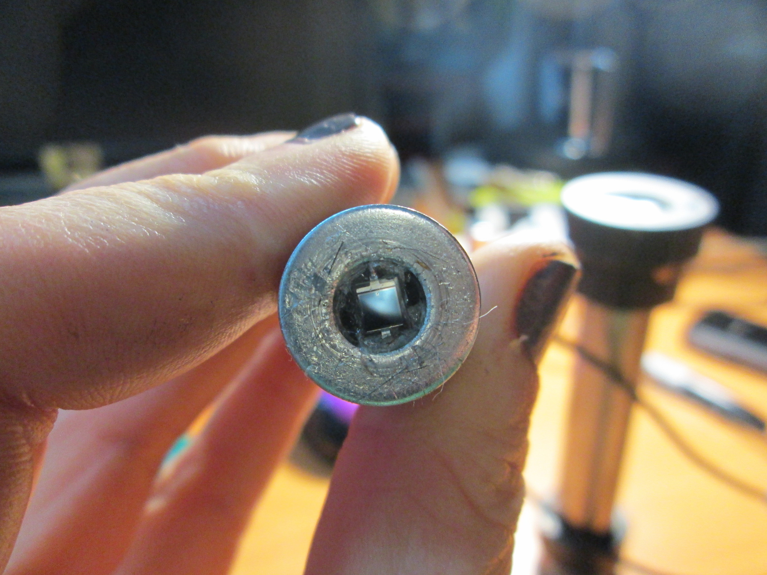
The photocell is creating a response from the input raster in the output raster, however it can only "see" blurry changes, it needs to be focused.
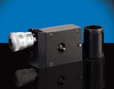
So- I made a scope with a lens to focus what the photocell "sees". It shelters the pc from ambient light and focuses the light...

I need the lens to reside exactly where the lens focuses - where the two triangles meet in the above diagram.
So this scope has adjustability in distance of the PC from the lens and is seated within a tube to shield the PC from ambient light.

The PC was not centered. The wires coming from the PC were, though shielded, weak. I replaced them with shielded audio cable (shielded- to reduce noise on the line- the PC provides super low voltage-).

I thought perhaps mounting the photocell into the scope I've made would improve the ability to see the "image" reflection. However, I might need to improve or change the lens of the scope? Here is what the PC "sees when it is merely seeing the raster scan from the HeNe:
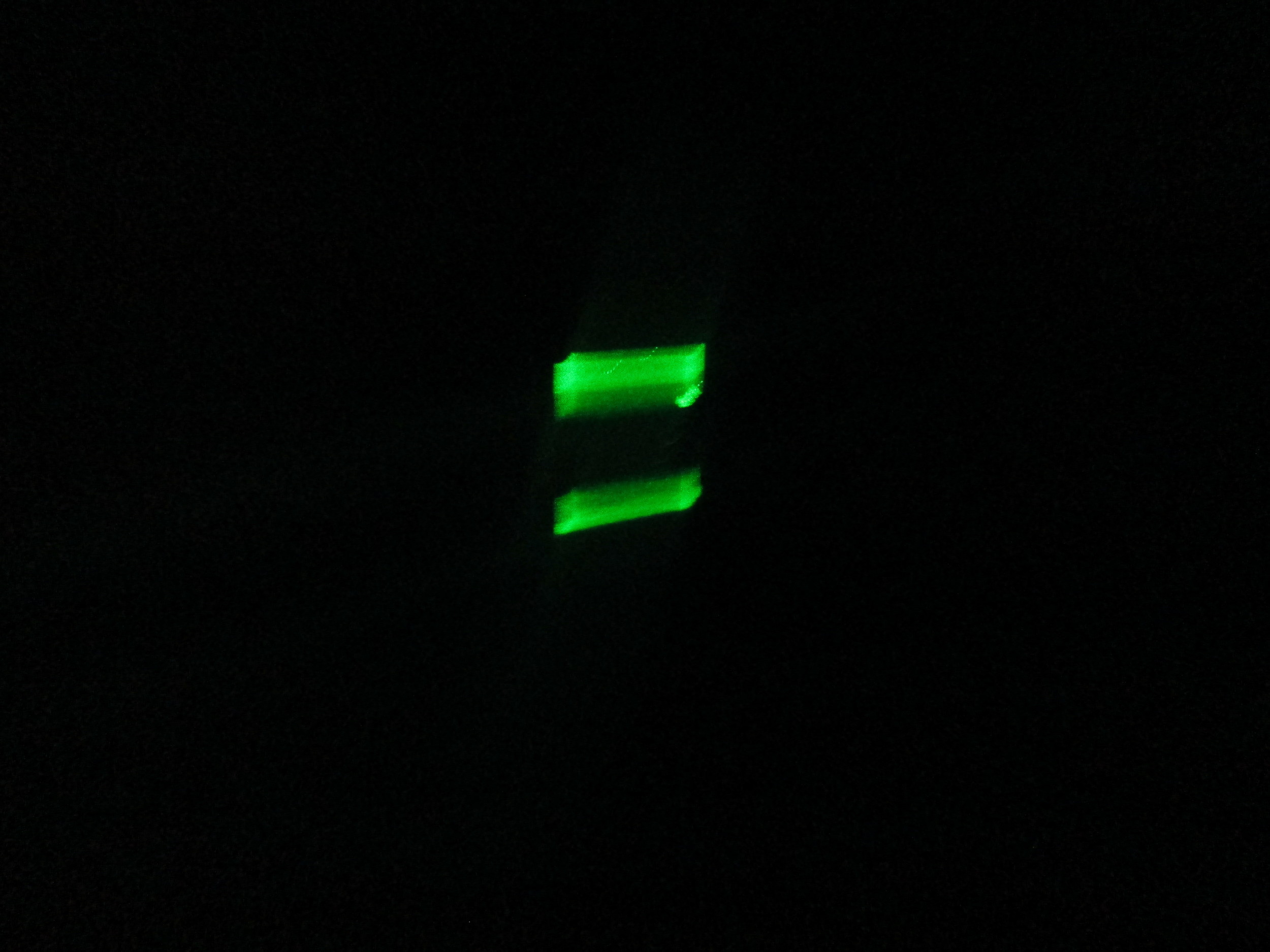
For this test, I had not focused the PC for the lens inside the scope. I should be able to see the PC in focus inside the scope, when I look inside the scope through the lens.

The circuit's inability to sense horizontal objects could be a compound issue of
A: the gain on the circuit does not allow for the photocell's reading to be interpreted
B: the horizontal lines are perfectly synced because both lasers' lines are generated on the same osc. mirror but the galvos are independently generating their vertical lines - though synced from the arduino- are still uniquely operating. To combat this issue I made a transistor circuit per galvo.
___
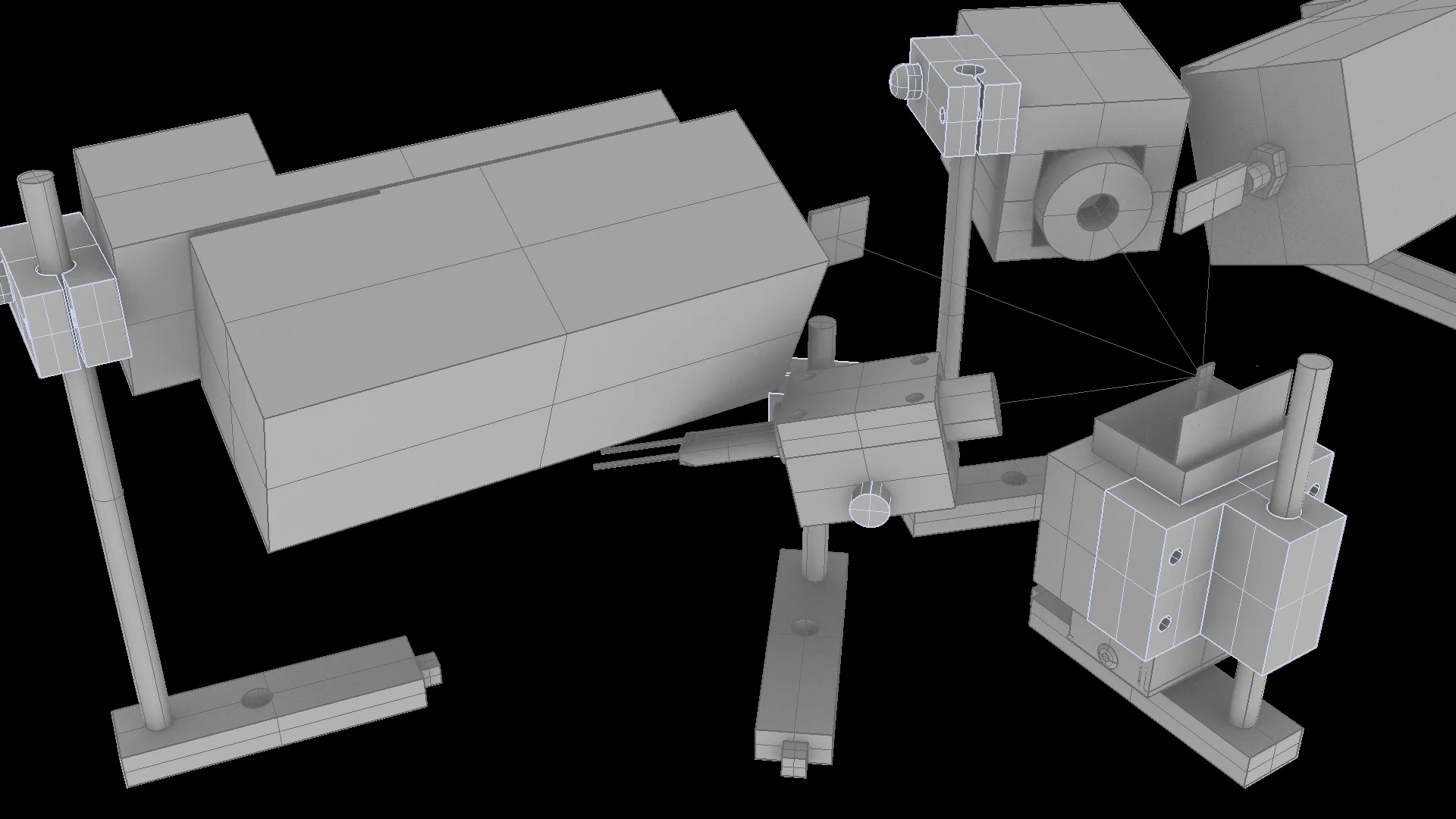
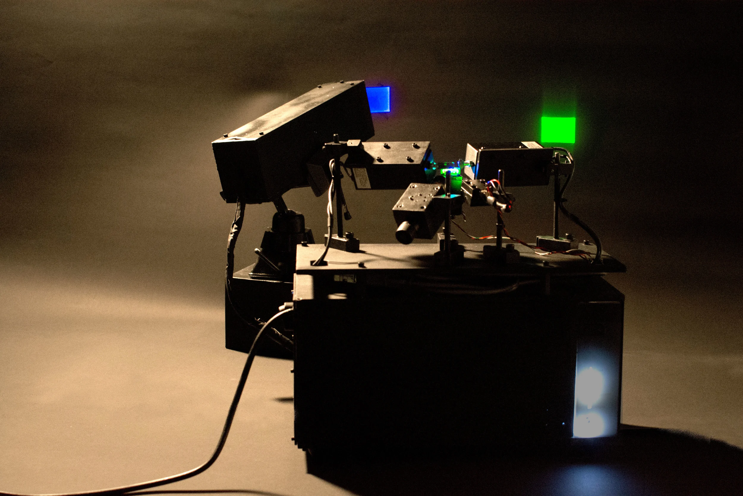
The Galvanometers are assuredly wrecked. It could be that I was driving them with too much current, it could be that they were damaged (I am very hard on my stuff),, or that how I had them housed caused damage. In any case, I have a new/ to me from surplus stock galvanometers. These are higher grade galvos, who should be able to perform in sync with one another.
These guys are going to take a bit of hacking to get going. .
Also, because of their size, the optical field needs to be a bit more complex. The previous plexi housing was problematic for a variety of reasons, mainly that it did not really hold itself well, and required constant adjustments. I have been toiling away in Rhino and SolidWorks to render the new optical field.

To better be able to hold the HeNe, I feel it is imperative that I remove it from its plastic housing (which is oddly shaped and bulky.) So, as i had two HeNe's, and because I am a dumb-dumb sometimes, one of these lost one of its mirrors, and isn't functioning properly... so I decided I could test rewiring etc. on this sad broken fella.
So I took it apart.

So, the galvos are funky. Coming from Surplus, it is to be expected occasionally.
I noodleed around... this stuff is rather expensive, but that being said I have spent a decent amount of money on surplus or short-cut options. So I decided to buy a used system with a driver that can be hacked, instead of building the system I need from nice components with no way of verifying that they function until much after the purchase date (delayed because of constructing drivers etc.)
So I found a galvo laser system on ebay:

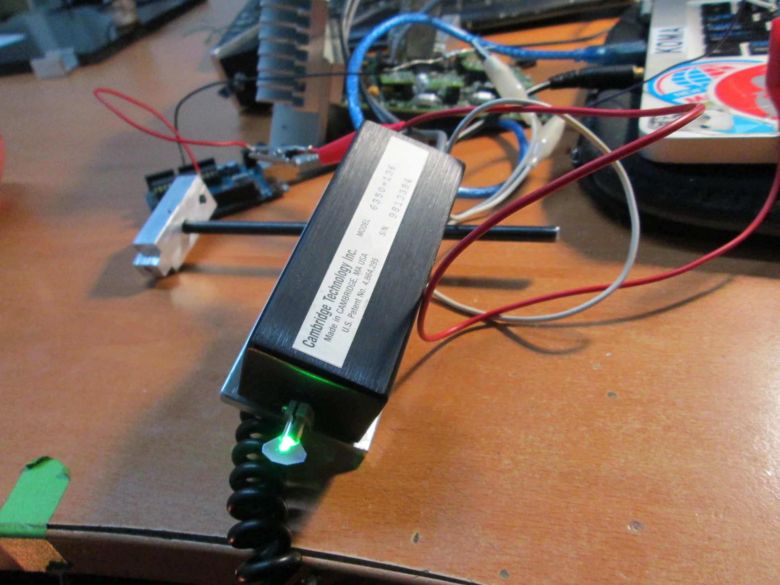
This is the driver that came with the two galvos. It is a General Scanning Driver - the same manufacturer as the galvos- Cambridge Technologies. Eric Rosenthal and I sat down and did several thorough internet searches for general scanning galvo drivers, (for you all coming to the same problem GENERAL SCANNING / LASER SYSTEMS DIVISION / REV A / SMALL SERVO / 222.295.00 are the bits of text on the board), we could find ZERO RESULTS which could clue us in on how Cambridge Tech powered and sent signals to the galvos via this board. So I emailed Cambridge Technologies:
Eric sat down with me the following week and we determined what we assume the power requirements are based on the regulators in place from the power to them.
There is a 7805 which outputs +5V from a higher voltage
There is a 7812 which outputs +12V from a higher source
There is a LM320-12 which outputs -12 from a higher negative source
I found an analog scanner's data sheet from Cambridge tech which took +15 and -15 volts so, because we know these voltage regulators want higher inputs than what they are designed to output, Eric guesses that this board likes +15/ -15v.

The grey wire coming out of the board is either signal In or signal Out.
Eric and I fed the driver board with +/- 15V and though the galvos engaged, they never oscillated.
However, when the power was cut- the galvos oscillated in accordance with the function generator's settings.
For my own reference- red is ground and yellow is signal. Green and black have some resistance between them, but these were not connected when the galvos oscillated (i.e. worked).
(BTW Eric Rosenthal is AWESOME)
So, for a back up and to be able to prototype the scanning system in tandem with breaking down how the driver actually works, I am going to see if the oscillating mirrors have any visual artifacts (i.e. are not impedance matched etc.)
Here is the machine list for the laser scanner assembly - sans the mounting plate.

I am beginning to mill the parts: Here are the brackets for the galvos.


I have begun to run the galvos off the arduino (arduino-as-function-generator). At first they were running high, too much movement. It tested at peak- 3~ v. So I put a resistor in line, and dropped that peak to .5 v. The movement was much better, more stable...
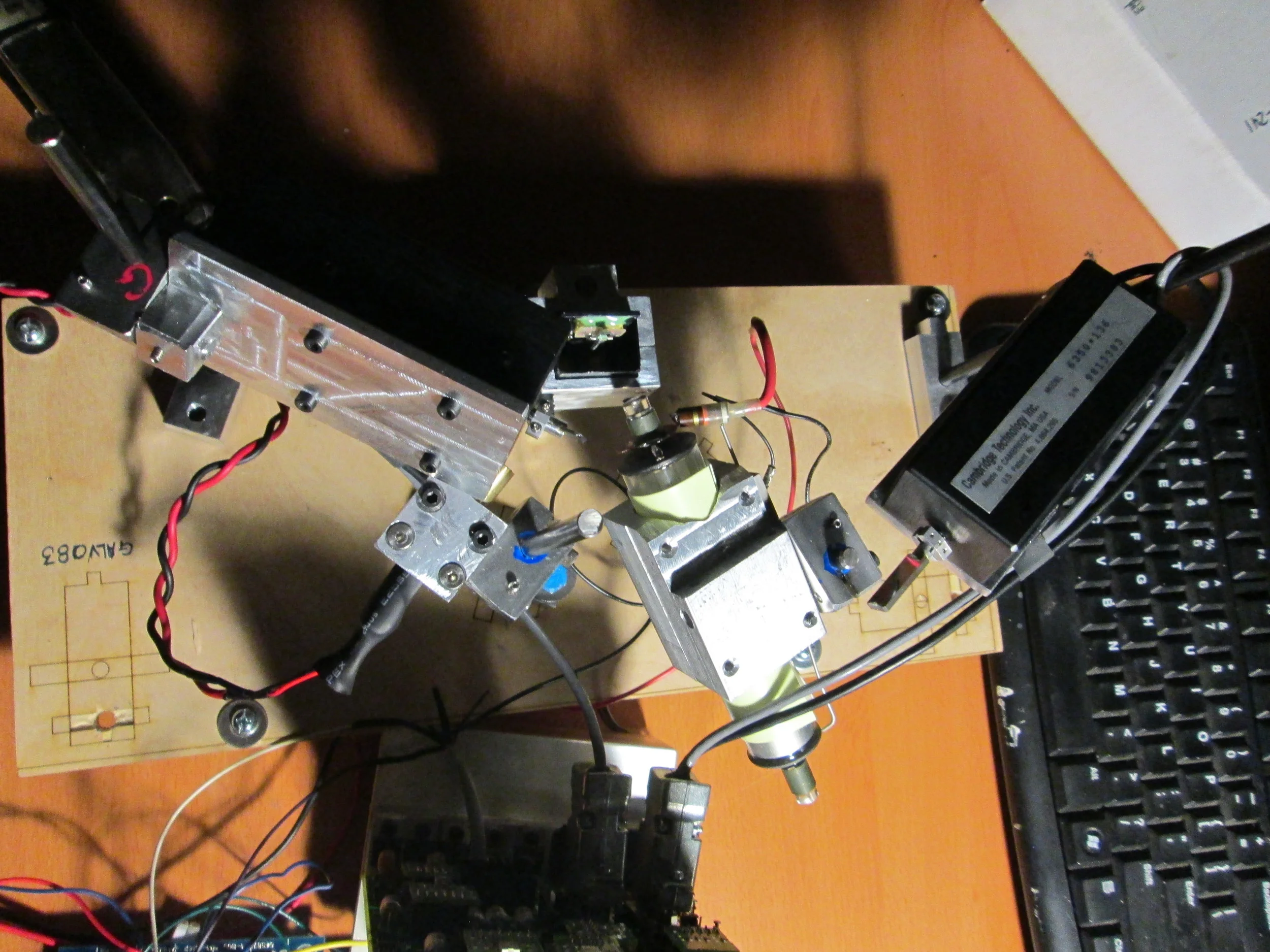
I assembled all of the machined housing on a temporary mount.

I have two sets of aluminum ready once I have confirmed alignment of the each component.

So the patterns present in the rasters (more apparent on the green raster) are a result of asynchronous movement of the laser (x and y). I updated the code going to control the galvos, and though it is better (the jumping, the size of the vertical movement etc.) it is not perfect. In the green laser raster the evidence of the laser going in phase and out of phase with the scanner is beautiful, but eventually problematic.
Moving forward, in parallel development.
The Photo Voltaic Cell is not sensitive enough to really capture anything from the HeNe raster. I have coming, from Z-Bolt, a 450nm 5mW laser diode coming to replace the HeNe, gorgeous and beautiful a Raster he makes, he cannot be modulated and illuminates a spectrum that silicone isn't friends with.
In addition to configuring and reconfiguring the driver circuit for the projection raster, Eric Rosenthal told me about Photomultiplier tubes.
They are one of the few "tube" technologies which have not been replaced by silicone.
Hamamatsu creates the quality standard fare in today's marketplace. As an aside to something really gorgeous, these have been flooding the market, largely because of these Neutrino Detectors being constructed, like this one in Japan:

So I got two in, both Hamamatsu. Most Photomultiplier tubes really like the 420nm range. Hence why I got the cheapest true blue laser diode I could find, so that should the PM tube become the way to go with photon detection, I have the right laser to work with it.


I will be using the first one photographed, as it comes with a pre-amp.
It requires 1000V DC.
How, in short Photomultiplier tubes work, is that a photon enters the face of the tube, the High Voltage going to the tube has very low amperage, but saturates metal flanges which attracts the photon. When the photon hits the flange, it collects some electrons and bounces to another flange saturated with electrons, and picks up some more, and so on, so that the photon entering the PM tube translates photons into voltage with a higher range than the Photo voltaic cell I have currently.
Photomultiplier tube wiki: https://en.wikipedia.org/wiki/Photomultiplier

So the Z Bolt Laser produces light at 450nm. To ensure that this sensitive detector wills see only the laser, I purchased an interference filter from a place called Anchor Optics.


I also got a 450nm bandpass filter from Edmund Optics http://www.edmundoptics.com/optics/optical-filters/bandpass-filters/experimental-grade-bandpass-interference-filters/28421/
What this will do is allow only light at 450nm wavelength through to the PMT.

So I made an enclosure strapping the head of the PMT to the bandpass filter.

I tested what the PMT would see with the Bandpass filter attached. It seems to reflect backwards about 1/3 or the Sapphire Z-Bolt Laser (http://shop.z-bolt.com/Sapphire-Presenter--Blue-Laser-Pointer-Nylon-Lanyard_p_245.html ).
Z-Bolt claims to be a true 450 nm laser. Edmund optics states their optic is also for precisely 450nm.
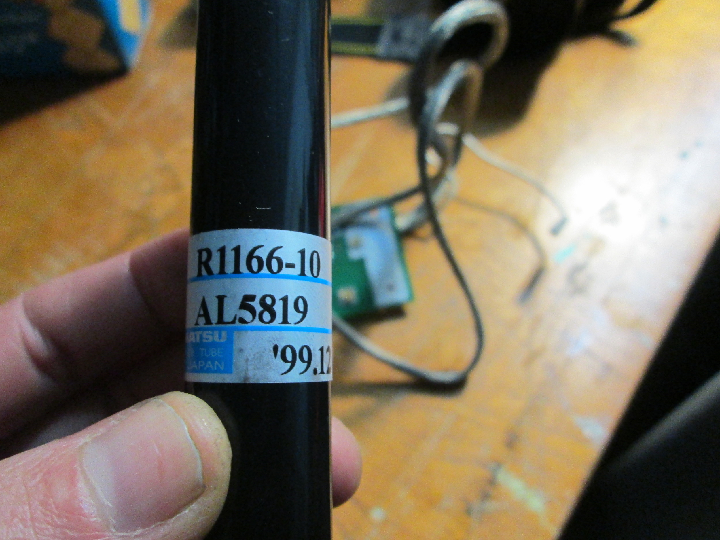
So, I tested the hamamatsu R-1166-10 with the Wallac Pre-amp in ambient light. It is quick to change but unresponsive to most other light (i.e. flashlight elicits no perceptible change, as it seems this PMT, though the datasheet states it can detect all wavelengths, it only responds to higher wavelengths...)
Note: the edmund optics filter did not cause changes on the output. this test was done without the lens.
When the lights in my studio are off, and I pass the 450nm laser in front of the PMT, there is no perceptible change. I suspect it might be that the ambient light (fluorescent) has some of the wavelength that this PMT wants to see, and the laser light mingles with it to amplify it enough to cause change on the output.
I fear that this PMT is truly seriously sensitive to UV wavelengths.
The datasheet for the R1166-10 states its "Spectral response : 300 to 650 nm" http://www.hamamatsu.com/us/en/R1166.html
This datsheet shows an un-housed PMT. The PMT used in the above tests came from used equipment and is encased in a housing and perhaps may have a bandpass filter within it on an unknown wavelength????
So I found on ebay another R1166 -- with no suffix numbers - and no housing...

Here are some white papers on PMT applications etc:
http://neutron.physics.ucsb.edu/docs/High_energy_PMT_TPMO0007E01.pdf
http://psec.uchicago.edu/links/pmt_handbook_complete.pdf
http://engineering.dartmouth.edu/~d25559k/engg168_files/notes/PMT%20Circuits.pdf
Also I began looking at other means of acquiring high speed high sensitivity to photonic changes, Avalanche Photo Diodes are a silicon high sensitivity components:
I purchased one of these, if not just to explore how it works:
I found some new old stock on ebay:

Here is a white paper on PMT and APD applications:
http://www.excelitas.com/downloads/app_apd_a_user_guide.pdf
and a nice video
Eric Rosenthal took spectrometer readings of my "450nm" laser and my "450nm" filter.
The laser's peak wavelength is : 447.87nm
the edmund optic only passes: 430nm
because of the specificity of the filter, I actually lose a great deal of information.
Rosenthal had a set of dichroic gels (a sort of test plastic gel assortment).
These apparently only let in a specfic wavelength, but they do not say this nm or that nm. Instead they have names like "sunset 8"
I have two filters which work (one attenuates half of the beam and one which begins to attenuate but ... )... So I need to do a trial
The two contending diochroic filters are : BLUEBERRY 8 / ROSEPURPLE 7


This is the current status of the project:
The circuits have been housed.
The PMT has a housing.
All metal is matte black to avoid wayward reflections.
The power supply is upgraded to two switching Meanwells wired to provide +12 and -12
Currently I am working on fine tuing the galvo suncronization with Arduino code.
I have a circuit I am working on to adapt the video amp IC (or circumvent it as the PMT can provide up to 1 and some change volts).
However, I had to bring this to O'Reilly's SOLID conference, so I ran the PMT signal through an arduino... i.e. not so great.
Forthcoming work is to hack a hard-drive arm and mount a super lightweight gradient - creating a chopper:

----
As an aside- for your photonic inquiries:
http://www.specinst.com/What_Is_A_CCD.html
For all of those buckets of photons:

Returning to the research and prototyping after a semi-brief hiatus:
The translation from PMT input to modulator circuit leaves me with generous lag times.
When discussing the lag time, Eric Rosenthal came to a brilliant experiment invloving 1960's era timing oscillators and mirrored finish.
Inside these crystal timers are comprised of a handful of items inside:
A housing- a layer of rubber- a metal (stainless?) ~1/16" thick or less, but not film or flexible stock- a thin and lapped piece of pure quartz- then another piece of metal, rubber and the other side of the housing. (there is also a spring inside)
Current is connected to the metal stock via the leads (lead a, metal stock a). When current is applied the timer is tuned to oscillate at the stated frequency. It literally shakes the quartz in a reliable and predictable way. It responds immediately, with minimal delays. Therefore, we are re-thinking the methods by which we modulate the "camera" raster.

We want to utilize the micro-instantaneous vibration nature of these components. Newer timers are tiny and hermetically sealed, which is makes them less useful than these older versions.
If I polish or somehow adhere a mirror finish to the layer of metal inside the crystal, I should be able to use that surface to bounce the output beam on and off the scanning component.

So I milled a slot in the rubber and metal housing parts of the crystal timer. This will allow the laser to hit the surface of the metal.
My next step will be to apply a polished surface or lap the metal to make it as close to a first surface mirror as possible.
Eric pointed me to this mercury like metal alloy- Galinstan (https://en.wikipedia.org/wiki/Galinstan)
It has some fairly reflective properties. It is an aqua-phile. Therefore my first step is to attempt to apply a thin layer of the material to the metal plate inside the crystal.
Bear in mind, Galinstan is quite corrosive to certain other alloys, especially aluminum. (https://uu.diva-portal.org/smash/get/diva2:728422/FULLTEXT01.pdf )

This means that in addition to the aforementioned plans, and the circuit required to drive the timer, (signal from the PMT), I need an optical slit.
Edmund optics sells these with micrometer adjustment for approx $400.
I don't ness. need an adjustable slit, just a very fine gap as the offset of the crystal oscillation will likely be minute. I will likely fabricate this if I cannot locate one on surplus shed's site.
____
So before going through the process of mirror finish application of the metal inside the crystal, I thought I would test the theory:

Despite the diffusion of the beam, I could still detect when oscillation occurred, by looking at the most concentrated part of the beam. It totally worked, at the first "ON" of the bench supply. However, no further instant oscillations occurred. My methodology for testing was to merely turn "on" and "off" the supply itself. Perhaps the caps inside the bench supply were still discharging.
I spoke with Eric, who advised I put a resistor between the leads to absorb residual voltage. He also recommended that I do not power off the bench supply, but rather clip and unclip one of the leads.
To test the application of Galinstan to the metal inside the crystal, I took a metal (steel) object, placed a bit of water on it, and with a clean, gloved, dry hand, I applied the galinstan to the metal.

as you can see it puddles up and has inconsistent surface. It isa lso not adhered at all to the surface, but rather held there by gravity.

it is an elusive material. :)
I waited for the metal to dry on the test material, and when I tipped it over to pour the material back into the vial, some of it timidly stuck to the steel. It was an easy to get off material, and so I thought I might try to adhere some to the crystal metal insert.

I waited for the water to dry and then poured the galinstan back into the vial. It kind of worked.

I then used canned air to try to spray it into a more even distribution. Some of the galinstan was adhered to the surface, but there was still some loose material on the surface. I sprayed it and moved the metal around ... it did even it out somewhat, but once the metal was turned against gravity, the loose material would seep to the bottom . So I turned to the canned air upside down, to ensure that the liquid inside the canned air would come in contact with the galinstan, and since galinstan likes liquid, ... it kind of worked better. I think a bit more tweaking and this might be the fix for the mirroring of the metal insert. If it does not stay adhered or other issues occur, I will simply buff the surface as much as possible.

I have a compression chamber access, so I might try to adhere some of this material to the surface with the compression chamber to generate an even distribution of the galinstan to the surface.
In the interim, I will attempt to oscillate the crystal.
As a point of interest, in my time working on t his project, I have been less than careful with my first surface mirrors. I spoke with a physicist friend who gave me very sound advice on cleaning optical mirrors:
Get some alcohol, preferably methanol but ethanol or isopropanol will do, but go with something pretty pure (especially for high power applications). Typically you place a lens tissue (I use thorlabs brand) on the surface of the mirror and put a few drops of methanol on the tissue above the surface of the mirror so that the tissue sticks to the optic. Then drag the tissue along its long axis rapidly enough that you see the methanol get pulled off to one edge of the mirror until it vanishes. The methanol is absorbed by the lens tissue and if you do it just right the methanol is completely removed from the surface of the mirror and the very edge of your lens tissue is dry.
If there is methanol left over on the mirror surface it will evaporate and leave a thin film, so just try it a bunch of times until you get it right.
If your mirror is really dirty and there are pieces of dirt that won't come off you can fold the lens tissue up a dozen times and grab it with some hemostats. Then put a few drops of methanol on the folded edge and drag it against the mirror surface with moderate force. If your mirror is in a hard to reach place this method works well as a final clean. Just make sure to drag across the surface once and don't reuse the same tissue. Also make sure you don't touch (with bare hands) any part of the tissue that touches the mirror surface because oils can just make things worse.
If you have lab grade qtips you can put a few drops on the qtip and drag it across the surface of the mirror while turning the qutip against the direction of motion. Make sure to rotate slow enough so that you don't touch any side of the qutip against the mirror surface twice otherwise you'll put dirt back on your mirror. This method is useful for difficult pieces of dust but requires multiple passes with multiple qutips to get the whole surface.
If there is a light piece of dust on a relatively clean mirror you can blow the dust off with compressed air (in a can don't use air out of a compressor) but blow lightly! If you use too much air pressure you can push the dust along the surface of the mirror with too much force and create a scratch.
If you have a coated mirror then don't worry too much since most coatings are pretty resilient. But if you have a gold or silver mirror that is uncoated they are more sensitive to scratches. A lot of people recommend that you just don't clean gold mirrors at all but replace them if necessary though I think this mentality is a little insane since I haven't had any serious issues with gold mirrors.
Anyway, do any combination of the above until the surface is mostly clean. Then finish with the tissue dragging technique for best results. If you need something more extreme such as a way to remove epoxy from a coated mirror you can soak the optic in alcohol for a while until it softens up. Dichloromethane works well for this but avoid acetone. Every case can be a little different ...
So I tried it out;


scratches persist. But gleaming *at least in comparison to before*!
07/02/2016
In reviewing status of the project where I left it before my hiatus, I realized that perhaps, the crystal as vibrator/chopper may or may not be the way to go. Eric Rosenthal helped me to develop the circuit which translated input from a photo sensitive component. It functioned, and began the initial "images" - however the sensitivity of the component was not great enough for my application. Eric consulted and helped me ramp up a Photo Multiplier Tube to stand-in for the photo sensitive component.
I hustled to get the initial project going for a conference where I was given a fellowship to showcase the device (O'Reilly's Hardware. Software and the IOT of things). In that hustle, I hastily tried to hook up an arduino to translate the PMT signal to the on/off pulsing of the output scan laser/ This is ineffective, shows change - but has serious issues.
For reasons which evade me, but logic states, that the voltage coming off the PMT was not similar enough to be put into the video amplifier circuit.
So for my next steps regarding the on/off modulations of the output raster, I will attempt to reconfigure the circuit made, and enable it to accept whatever signals come from the PMT.
In addition, a quick fix for driving the Galvos was to hook up a "tone" function from the Arduino.
The proper way to do this is to divide the Resonant Scanner's frequency in circuitry. This way, no artifacts will occur.
I first explored using 555 timers, or sourcing a crystal oscillator at the correct frequency. However, over time, these might become asyncronous. Therefore, pairing the perfect and easy to hone to specificity, resonant scanner frequency is the way to go forward.
My husband is an audio analog synthesizer enthusiast and linked me to a circuit he had been planning on building for some time now:
http://www.cgs.synth.net/modules/cgs36_pulse_divider.html
So I will use this circuit as a template to provide a synced frequency signal to the galvos.
Finally, I need to clean and reorganize the housing, and components. Upon attaining these or merely attempting these upgrades/actions, I am certain more obstacles will present themselves Ultimately, this project will require a holistic upgrade in order to achieve the scale and detail I am interested in. I do see this leg of the project as a prototype for a larger version.
The aim of this prototype is to get a real-time camera/video projector.
So, now let's dig into the aforementioned plan!
I am at a Signal Culture Residency in Owego New York Some Decade Counter Research.
My first task was to make the galvos sync with the scanner. At Signal Culture, there is a volunteer on hand for the residents (http://www.jonesvideo.com/) who made a nice Pic Chip device for me which used the TTL output from the scanner as a clock to create a square wave at the frequencies needed.
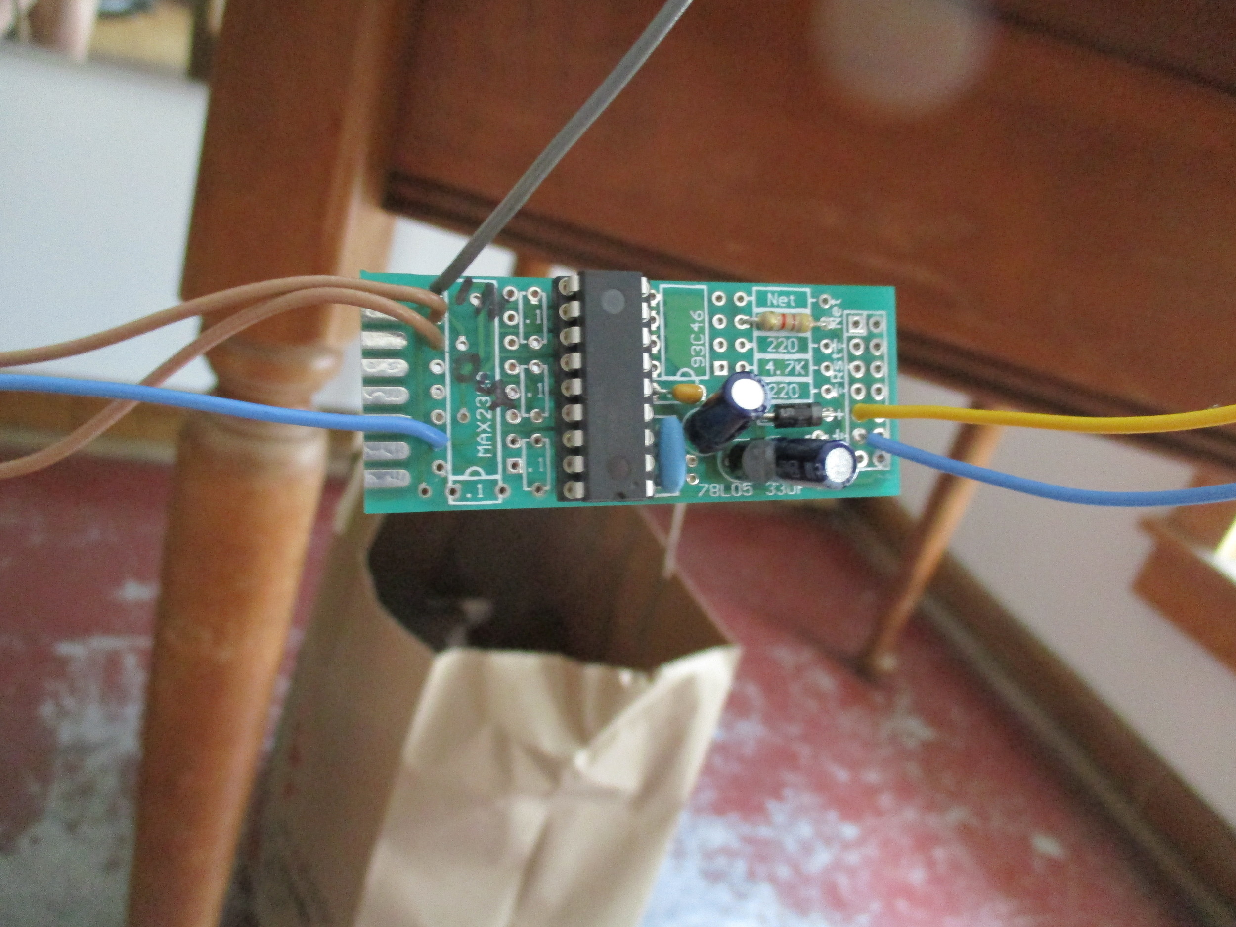
He also advised me to not use decade counters, but instead, to use binary counters.
The signals are output at a 50% duty cycle and output approx 2.7 vdc

The output of the Pic Chip provides an option for 2 divisions- one providing me 60fps and one at 30fps.
Here is a nice breakdown of decade counters:
https://www.youtube.com/watch?v=XyWahsjzuek
The decade counter waveforms appear as:

And the output of the binary counter would be as such:
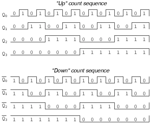
Mr. Jones explained that the binary counter is more simple and on point than the decade counter, as I am limited in what divisions are available to me.
In addition, he states that the circuit needed to do this calculation is half as complex.
---
I hooked up the Pic Chip to the galvos and got a pretty artifact free scan.
The scans continue to jump (i.e. scans are artifact free, but their placement jumps )
<<<insert Video >>>
In addition to the synced signals for the mirrors, I also need to insert the PMT signal to the amplitude circuit Eric Rosenthal designed.
Mr. Jones showed me a service manual for the AVC-3400 tube-based portable video camera. - SUPER COOL!

I am particularly interested in the amplification section. Mr. Jones said that he thought the input from the Tube was likely in the super infinitesimal and that these transistors amplified the signal. Which is exactly where I am in my circuit.

First Draft of a PMT modulator circuit. The previous circuit, obviously, was designed for a photo transistor. A PMT does not ness. require all of the bias -
So Eric suggested this circuit from the AD818AN datasheet.
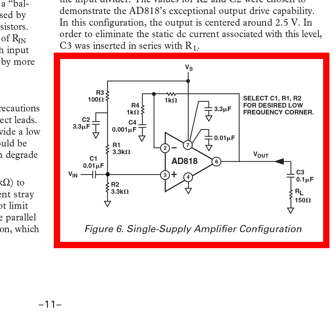
So I mocked it up with the freq. generator- feeding approx 500mV

and we have output! - feeding 500mV square wave and getting a 12v square wave! (channel 2 is my output - the blue)

This circuit was not working correctly. Eric recommended that I build the circuit with a tighter design- as the high frequencies that the circuit is designed to amplify.


The circuit attenuates the signal coming in from the function generator. So, I tied ground coming off the bench power supply to ground. Even though the circuit has some filtering caps on the Vin pin, I also added a 10 mf cap across Vin and GND. The attenuation, still occurs - but is less than before, which leads me to believe that this attenuation is caused by too many leads from the components- that I need to chassis ground the circuit to a ground plane, and tighten the circuit even more.
Because of the length of this blog-post and the weight of it when editing, I am starting a new blog post which will reiterate some of the research done up to this point, but will start from here.
Please see
https://hannahmishin.com/blog/2017/5/28/laser-scanner-camera-projector-v2
, _____