CONTACT
I want to capture the inherent resonances in everyday banal properties of the buildings we inhabit on a daily basis. Meaning- Enliven the ordinary objects/structures/infrastructures- to give emphasis and life to these aspects of banality of day-to-day living.
These microsounds will be given poetic synthesis (retaining their inherent properties but captured, amplified and enhanced)- for compositional and poetic qualities.
The resulting environment should be immersive and wholly engaging, which allows individuals to be subsumed by the marrying of human spaces and human qualities. This sound should not be invasive to the room, but provided within the room/space should be an allocation for dissolving into poetic banality.
inspiration:
David Byrne- Playing the Building (using LEMUR design)
http://www.davidbyrne.com/art/art_projects/playing_the_building/
LEMUR
http://lemurbots.org/
Soundwalk Collective at Berghain in Berlin --- Resonances (this sound was like nothing I have ever experienced before.
https://soundcloud.com/soundwalk-collective/berghain-vibrations-resonances
PLAN:
Map the entirety of public space of ITP's 4th floor.
----map the pipes (follow them throughout and see their inherent network)
--map the vents...
----map everything in the ceiling.
Locate and document all surfaces on the floor which are above a secific height
--brick- different kinds of brick---glass-- metals and their various kinds and thicknesses and shaps
Collect field samples of all automated sounds
----differentiate between human automation and machine
To articulate the sensor array needed, it must be based on observations of human activity in the pulic areas of the floor.
---observe the different patterns of human movement on the floor (pace- quantity etc.)
Finally experiment with different acutuators on the various surfaces of the documented areas of the floor. Sample them and attempt to gather the best actuator and then amplifier for their properties.
Below is the ITP floorplan- with the areas I want to create the above network.

the above maps are of actuators/ below is a map of human/mechanical automation which I hope to contact mic.


breadboarded audio-phile pre-amps for piezo contact mics.
Below is the circuit for the bread-board-ed preamps above

And the parts list for the circuit:
1/4" slim line phone jacks (2)
10 uF electrolytic capacitors (2)
1k resistors (2)
10M resistor
PN4393 JFET, TO-92 case
Box 546-1551KBK
Battery snap
Piezo pickup element (2)
Nut for jacks (2)
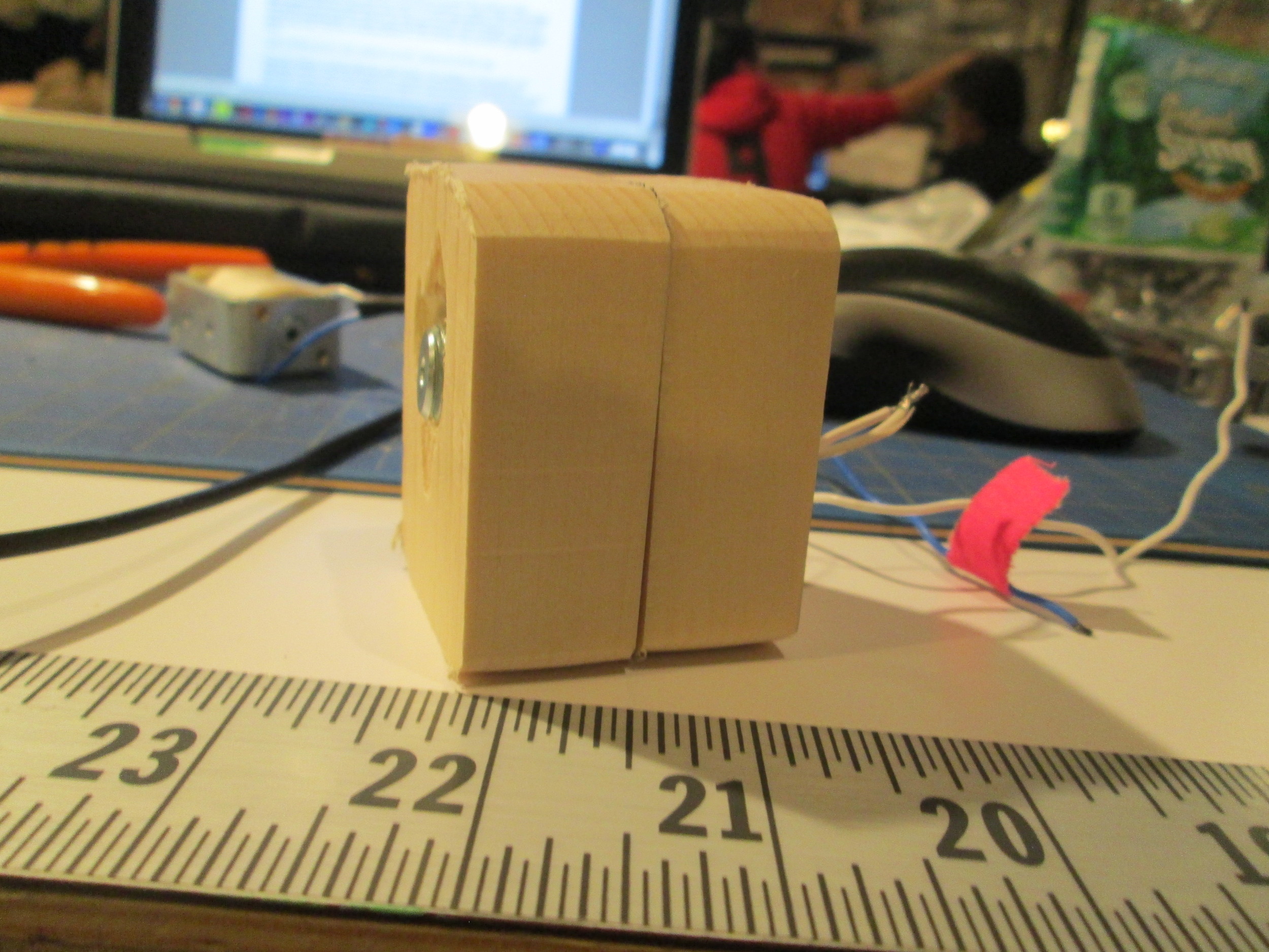
and then I made a little solenoid housing.

took some sample field recordings from a simple contact mic.

14 hours of trying to get the amps to work... lots of feedback on the lines, and low low input from the piezo.

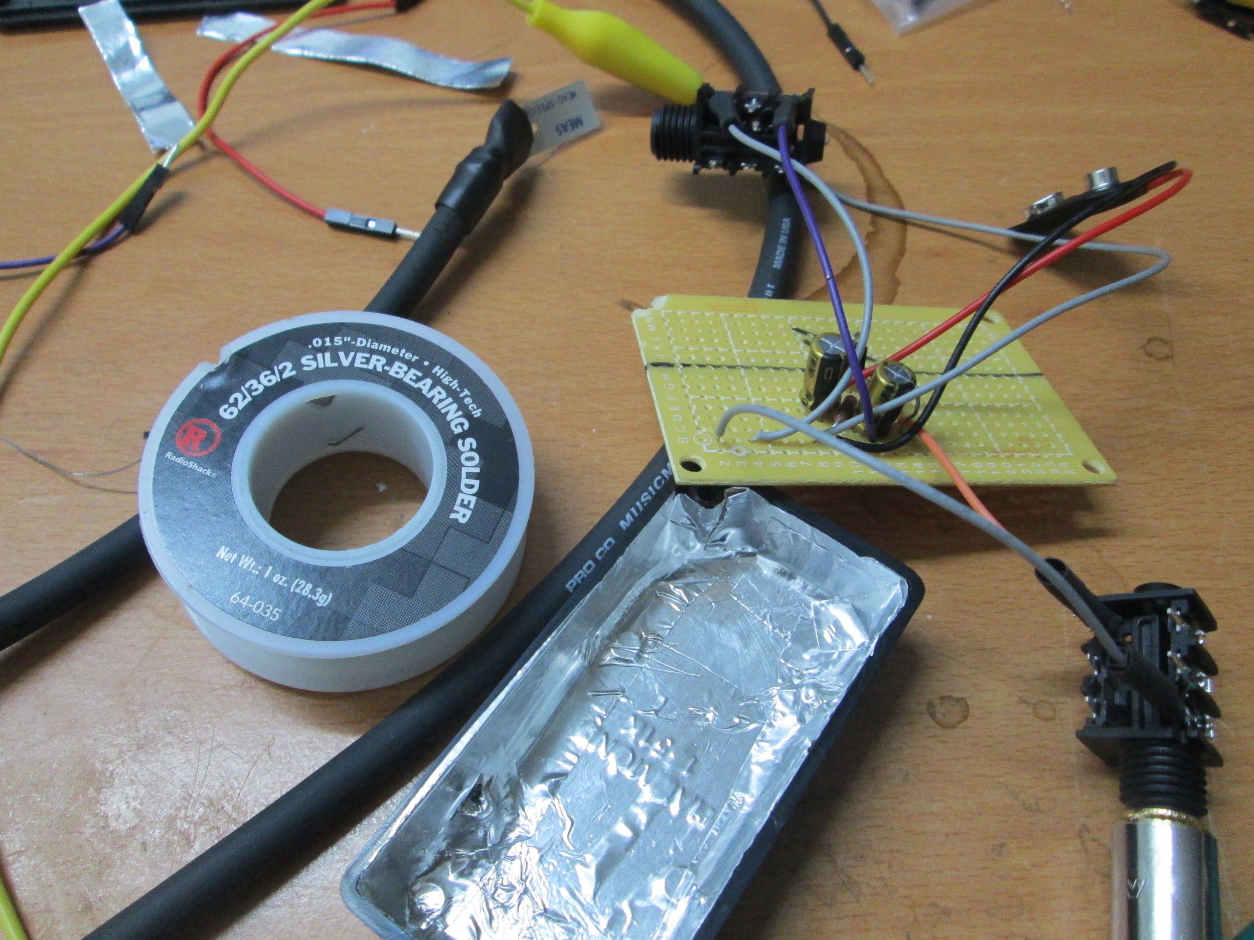
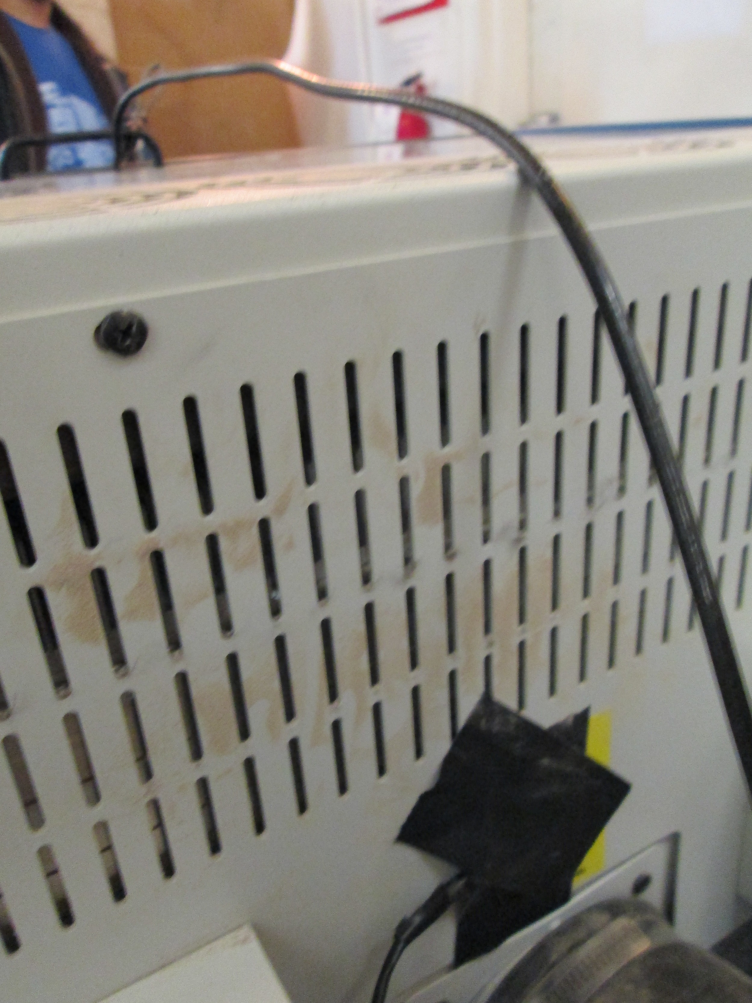
still problematic, but I sat with a sound guru (Boris), and we got to the impedance matching, as there is a voltage divider in the amp which was created for a specific input and I was using a different piezo. We hooked up a MEAS (see below photo) and it worked like a charm. Then Boris explained how most professional audio equipment is grounded through its carriage. Meaning it attaches the ground to the outside metal housing, which eats most of the electrical noise in the audio circuit. Also, he lent me some audio cable which is well insulated, to keep the cable from adding noise on the line, as the metal piezo disc was also acting like an antenna. In the below photo, note the case/housing wrapped in silver tape. I have a ground wire ready to solder on once I get the perf board cut to size.
So, perhaps I can achieve a pre-amp like thing in software- using FFT.
Here are some links on using FFT in Arduino- I found them helpful
http://forum.arduino.cc/index.php/topic,38153.0.html
So, my first question is- what is FFT-
A Fourier Transform converts a wave in the time domain to the frequency domain.
The above is from this link- it explains fairly well what FFT is...
http://www.alwayslearn.com/dft%20and%20fft%20tutorial/DFTandFFT_BasicIdea.html
Here is a post about the math involved involved in an FFT- (I must admit- it is difficult- for me, but this post helped me understand it astractly--):
http://www.katjaas.nl/FFT/FFT.html
So in the interim, i decided it would be prdent to begin taking sounds into my machine and seeing how the resolution is. I also knew that I would need to begin trouble shooting the mounting of the actuators and mics.

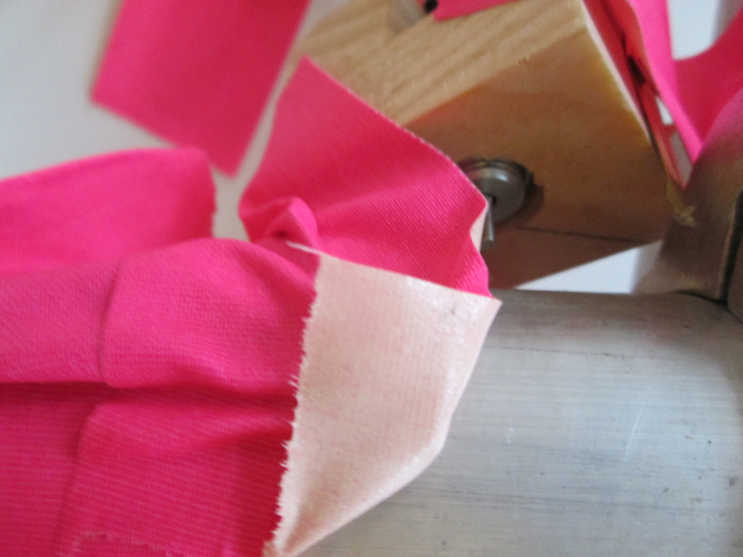
Tape isn't cutting it, and I knew it wouldn't ... each solenoid needs specific spacing
per each object it hammers. Above is my solution to this... now to mount it securely but not permanently.
Above is a sample track of two solenoids randomly firing, one on a vent and one on some speed rail in the ceiling of the student lounge. I recorded these with a zoom recorder and fed them directly into Ableton Live and executed a simple EQ on the field samples.

So after much deliberation, I've decided that in order to achieve an accurate live processing FFT, a single arduino will not provide enough processing power for 16 inputs. Therefore, I have ordered 10 bootloaded ATMEGA chips from Adafruit (https://www.adafruit.com/products/123), some crystal timers && voltage regulators (16 MHz clock crystal && 7805 Voltage regulator). I ordered 10 PCB boards from Modern Device (http://moderndevice.com/product/rbbb-pcb/) (see below).
I will build the boards based on the tutorial on ITP's p-comp site:
http://itp.nyu.edu/physcomp/Tutorials/ArduinoBreadboard

These arduino pcbs will be entirely responsible for processing the FFT. These (*I hope) will be fed into a single arduino which will accept the transformed signal as digital and send it to Max MSP.
The above video is processing of an FFT on the piezo and Max reproducing the sound without the IFFT. I was just so excited to see the FFT working in Arduino and passing all of the values to max that I posted this.
The above is a max patch that Andy Sigler wrote for me. I was attempting to run the IFFT (Inverse Fast Furier Transform) in Max. The code I found, and for the most part, all code, handles only the Real Output from the magical math but it also generates imaginary outputs. The IFFT in Max needs that array. So ...

So, stackoverflow--- http://stackoverflow.com/questions/9453714/converting-real-and-imaginary-fft-output-to-frequency-and-amplitude

Here is the code provided by the FFT library examples.
(http://wiki.openmusiclabs.com/wiki/Example)
A download of this particular library (as there are many )-
http://wiki.openmusiclabs.com/wiki/ArduinoFFT?action=AttachFile&do=view&target=ArduinoFFT.zip
On the right is the code- with lots of syntax that is unfamiliar to me and on the left is the ReadMe file in the FFT library.

Above is the Max MSP patch that Andy Sigler wrote for me. The IFFT requires both the real and the imaginary outputs from the FFT processed in the arduino.
I was not sure that I was sending the imaginary output. FFT processes both real and imaginary outputs. It seems that most applications use FFT to visualize audio signals in some way. For these purposes, only the real output is required.
The Arduino code above stores the real outputs in the even numbers of the array and it stores the imaginary in the odd numbers of the array.
The Max Patch sorts the incoming array accordingly and allows me to have separated values for the imaginary and the real and feed these into the ifft~ object in Max.
Here is where the process is problematic. The Arduino FFT is successful and the Max Patch recreates the signal into wave form. The window size that this code produces is such that it does not give the fullness of frequency ranges that would be adequate for a full audio analysis and re-creation.

This bit of code - and the library written in machine language- are dealing with byte and bit sizes.
A byte is composed of 8 bits.
A bit is a binary 0 or 1.
It is reformatting the ADC data into 16 bits or 2 bytes....I think.
My window- which is the fft_input- which contains 2 16b values per fft data point. (1 imaginary and one real)- limits the window size.
fft_window() - function multiplies the input data by a window function to help increase the frequency resolution of the fft data.
However, when I go into the Arduino code and attempt to change the FFT_N 256 size from 256 to say - double - 512 (meaning, I think, that the array would then hold 1024- because of the real and imaginary) it won't compile because of the bit of code directly above.
Therefore I need to find a way to increase the window size of the FFT and I have no idea how to do this or if it is possible.

So, after having 7 individual mics, I have determined that there is a richness to the floor's automated sounds which i feel actuators would lose. (the glitches in the sample recording are from my use of a firewire hub.... without that hub, The sounds of the floor are gorgeous). The video above is an example of how I want to treat the sounds I collect. However, I will not know where the person's head is when listening to the floor.
(in other words, I want to place the sounds from their origin in auditory space- if the faucet lives - when facing tom igoe's office- to 2 o'clock- then the sounds from the faucet should also live at 2 o'clock).
But people are people and they move.
So what I want to do it know where they are looking when they have the headphones on, so I purchased a gyro/accelerometer IMU breakout board. I got a generic brand (MPU 6050) for 4 dollars and six cents (the comparable board sells on Sparkfun for 40.$)
http://www.amazon.com/SainSmart-MPU-6050-Gyroscope-Module-Arduino/dp/B009A526M6
I found a great deal of information about the chip and code and libraries. I am putting them here for reference:
http://www.geekmomprojects.com/gyroscopes-and-accelerometers-on-a-chip/
http://forum.arduino.cc/index.php?action=profile;u=187766;sa=showPosts
http://playground.arduino.cc/Main/MPU-6050
http://www.varesano.net/projects/hardware/FreeIMU
http://www.i2cdevlib.com/
http://playground.arduino.cc/uploads/Main/MPU6050-V1-SCH.jpg


I ended up with 24hrs of continuous recordings of the floor.
Now, what to do with the post of this?
So I began by taking shots of the wires which travel along the ceiling to the source.
An example of this (edited)
My first sketch of the visuals
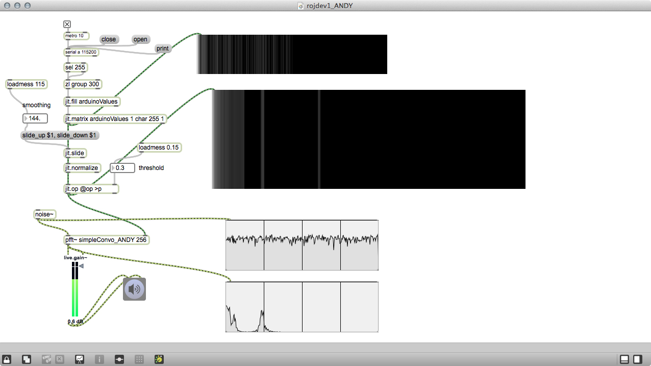
and so I return to FFT- this time for visualization- I wanted each channel (representing each mic) to pulse with its own fluxuations.
Below is a sample of a processed channel.
I realized I was being daft in trying to analyze the videos with the FFT code individually. Instead I decided to run them concurrently.