Arms
I laser cut the parts to the 123D cut-list and prototyped it with cardboard.
I then glued it with rubber cement. The areas I cut out with Z-Brush (edited mesh) - articulated areas- created interesting cuts in 123D make.

I did not track the finger section as closely as the arm sections, and got a little lost in the puzzle mess I made.
Hence this arm will remain finger-less. I have them for sizing (dowels and joints) later in the process.

I also began working on the specifics of the motorized joints.
I have a pan-tilt servo mount and am finding difficulty with mounting it for prototyping the movements.
I built a box.
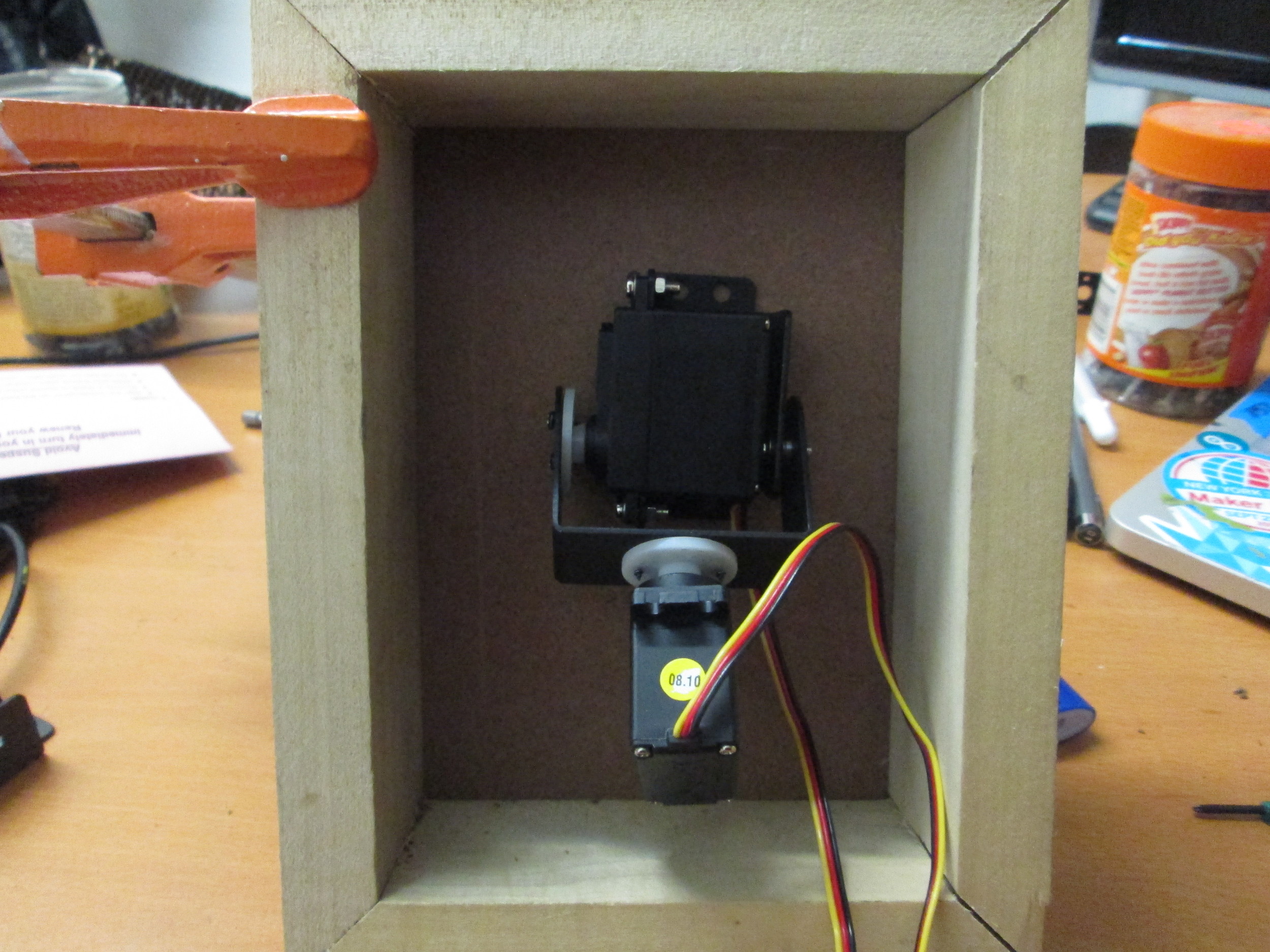
There were issues (apologies for the blurry photo):

The movement with the flexible attachments did not allow the "arm" to articulate fully. It gave a fluidity of movement but limited the range.
So, I then moved one of the servos in a different configuration:

The servo was mounted onto the 2nd to bottom section of wood. Attached to the servo's circular section is another bit of wood with the universal joint for the side-to-side motion and used the pan-tilt brackets to control the upward motion.
There is still a limitation.


The arm, once controlled by arduino, had not enough torque to lift the arm once it was completely down. Therefore I decided to mount this completely differently, and use the pan and tilt directly.
Though hesitant to relinquish the naturalness of the movement allowed via the universal joint, I mounted the arm and joint onto the servo pan/tilt
Alas- when the brackets are raised vertically, the universal joint counteracts that motion- thanks gravity.

So I thought perhaps to use the servo gears to assist me with anti-gravity.
By adding a larger wheel on the side of the up/down servo-bracket and looping the attaching "ligament" material to the arm, through the loop and onto the side of the bracket, I could make this actionable.

The brown wheel attached to the side should spiral around and retract the rubber -ligament sufficient enough to pull the "arm" up.

This did not work either.
FINALLY-
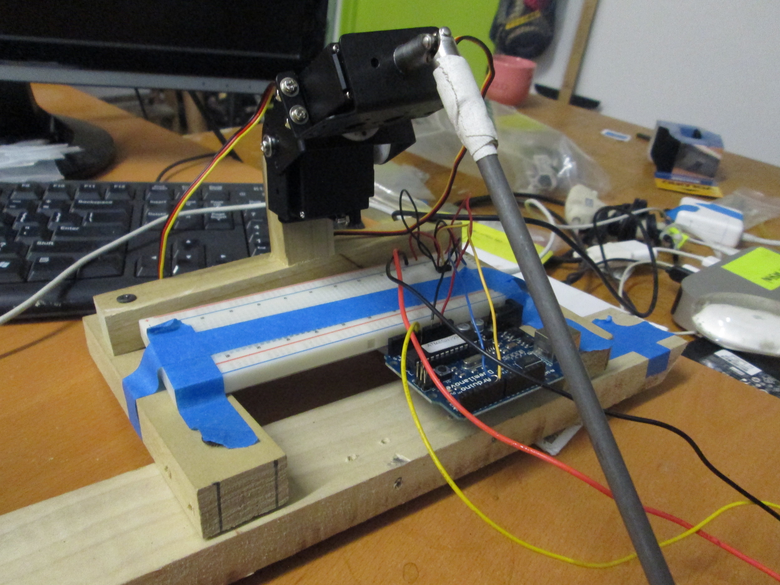
I replaced the string/rubber with rigid hemp rope. I returned to a prior set-up and based on advice, I moved the "pulling" servo farther back and extended it so that it could have sufficient torque to lift the steel rod.
Though it is difficult to manipulate a potentiometer and capture the entire action, when the dowel (driving arm) moves upward or downward in particular configurations, the steel rod has a buoyant-quality - natural mimicry.
Parallel to this development, I have begun editing the 178 files that 123D make generated for me, and have start the process of glueing the 3 thousand or so sheets of paper which will be the arms' skin.


I made a 3D drawing to print, a bracket to hold the arm in place against the dowel-

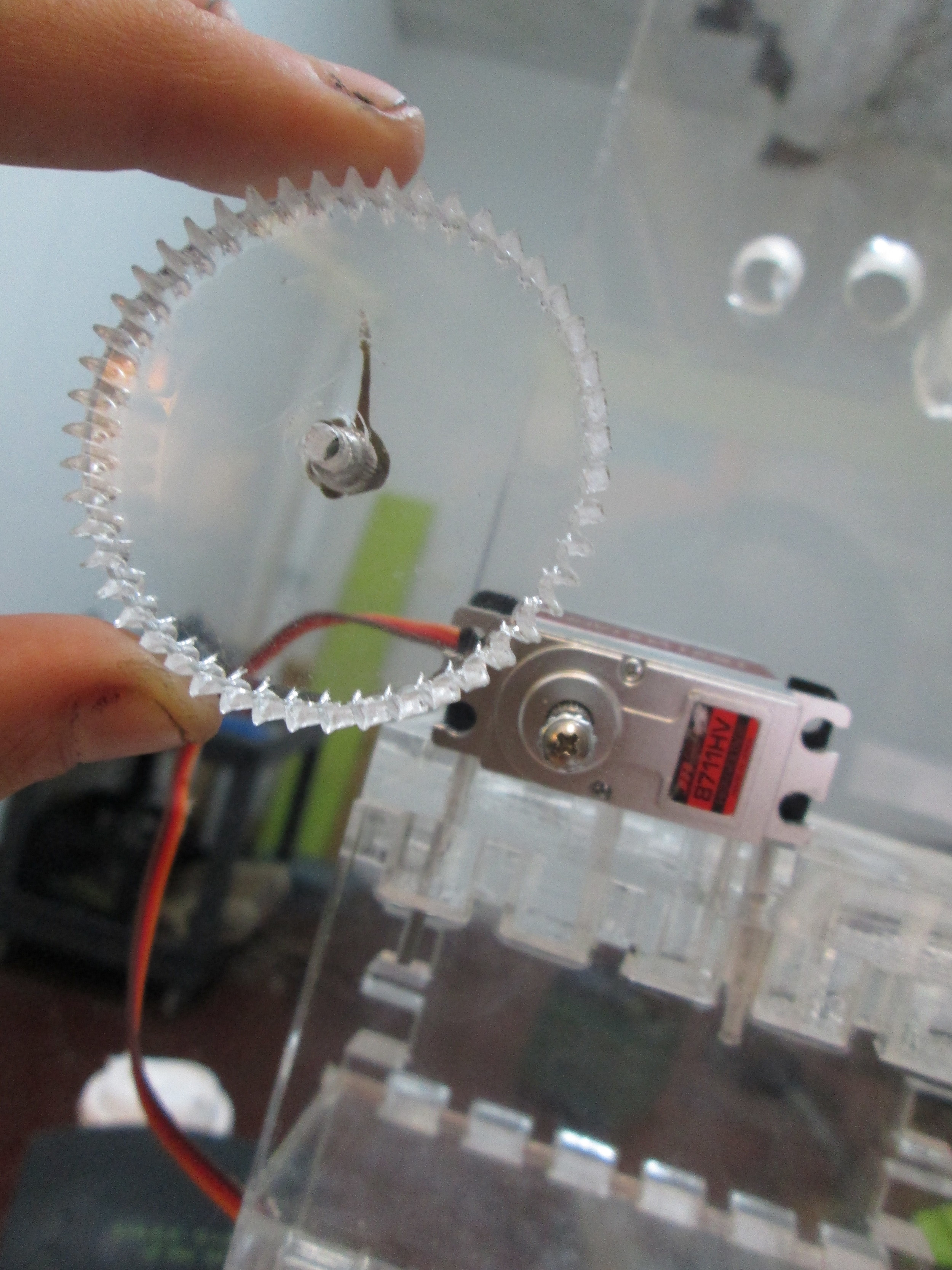
My main issues have - thus far- been in mounting gears and having them align properly:

I needed to make a permanent enclosure and rid myself of this shanty town;

I inserted the brass rods- pressure fit accordingly- but alas, the bushings et. al. were not secured enough (despite rubber mallet implementation):

I made plastic bushings and glued it all in-

I also bought myself a fancy high torque servo-

the first iteration in action-

Was working on the code to communicate with Kinect, when ... the torque of the servo snapped the 1/2" gear shaft.

Was working on the code to communicate with Kinect, when ... the torque of the servo snapped the 1/2" gear shaft.
So to begin about re-designing the housing- I took off the small gear from the servo. It proved to be much more easy to remove than I had imagined, despite the JB Weld.
I am printing brackets to house the exterior of the arm.
