Step Motor Research
My next project involves Stepper Motors, many of them in fact. So in preparation of this project, I have sourced many different types of stepper motors available to me and within my price range.

2 motors wired differently
I purchased one of each of these:

Wantai- 42BYGHM809 a 2 phase 3V motor from Sparkfun

SM-42BYG011-25 - a bipolar 12V 2 phase stepper motor - from Sparkfun

Wantai 57BYGH420 - Unipolar 3V 4 phase from Sparkfun

39BYGL215A- 2 phase 12V from sparkfun

Vexta PK564-AA- a 5 Phase 10 lead motor 1.7V. from MPJA
Some notes on this motor. It is a 5 phase stepper motor. This means it has the ability for acute accuracy ... however, it is more complex to use. I doubt my project will require a 5 phase motor, but knowing how to wire it and program it is important.
Therefore there are links below which will describe the code and the schematics for the wiring and driver circuit.
EXAMPLE CODE:
http://forum.arduino.cc/index.php/topic,160588.0.html
WIRING OF MOTOR GUIDES:
http://forum.orientalmotor.com/viewtopic.php?f=3&t=468
http://www.cnczone.com/forums/stepper_motors_drives/51130-vexta_5-phase_10_wire_steppers.html
DRIVER CIRCUIT:
http://ravith.files.wordpress.com/2008/02/driver1.png


STP-57D211- a unipolar 2 phase 3.84V from MPJA
To better understand stepper motors- sparkfun has an explanatory video:
There are two ways to communicate to stepper motors with an arduino:
The first, and "easiest" = the Easy Driver breakout board


The bonus for this board is that it requires, per stepper, only two pins. However, the cost for each driver is ~15 dollars. If using many steppers, the cost per motor, with this driver would increase the cost of the project.
a good blog on using the easy driver (with code) can be found here:
http://bildr.org/2011/06/easydriver/
The alternative would be to use L293D dual H-Bridge at a cost of ~2 dollars per unit.


From The ITP PComp site: https://itp.nyu.edu/physcomp/Labs/StepperMotorControl
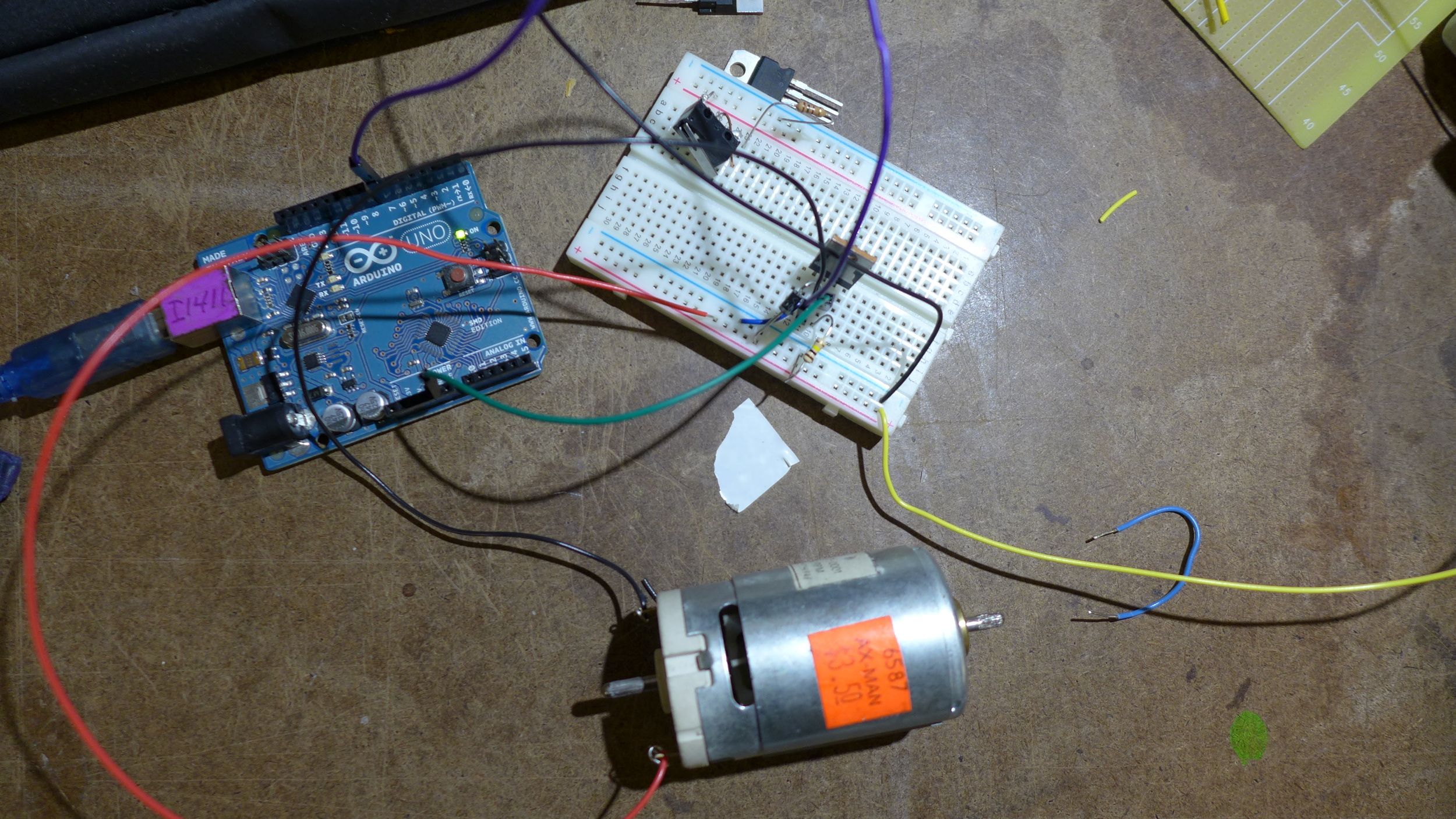
So I hooked up two motors - one on each type of driver and powered them.

My first fritzing - kind of sloppy- here's how I hooked up my drivers/motors
Then I hooked up two steppers to two separate dual H-Bridges and synced the two differing steppers.
These just happened to be in sync... but I need to automate their synchronization....
When I worked on Ohm Wrestling, I mounted a pololu IR sensor on the arm mechanism so that the DC motor would know where it was in the half-circle space it was to move within. We basically made a crude rotary encoder. I can implement the same sensors and code for this purpose as well.
Here is the sensor- a QTR-1C reflectance sensor.

Here is a link to the GitHub containing the entirely essential library from Pololu:
https://github.com/pololu/qtr-sensors-arduino
The Library uses some mathematical functions and is built to easily implement an array of these together.
I highly suggest reading this before using the sensor.
http://www.pololu.com/docs/0J19/all#3
An encoder is a simple black and white which passes in front of an IR sensor (like the one mentioned in this post). The IR senses the changes in white and black (reflectance) of anything passing in line of the Infrared sensor, and detects when there is less reflectance (i.e. the black surface on the encoder below).

If the IR were spinning in a circle around this encoder it would know when the motor is in the "top" (based on orientation of the image above) and when the motor is "below" the mid way point. This particular application could be used to tell any motor to only rotate half way - and when sensing a change- reverse direction - rotate another half way - detect change and repeat.
These encoders can provide so much more information than my application required. They use something called Grey Code- a binary system-
https://en.wikipedia.org/wiki/Gray_code#Position_encoders
NOTE: For more intricate encoders, ones where more positions are required, there are many fancy varieties. I stumbled upon this link:
http://www.bushytails.net/~randyg/encoder/encoderwheel.html
(I have not tested its output)- it allows you to configure files to make your own precise encoders for these kinds of applications.

Then I remade the circuit on perf board.
The stepper motor I needed for a project required a super high torque motor. It requires 1 amp per coil to function, and the higher the load, of course, the higher the amperage needs of the motor.
The H-bridges are not rated for the amperage requirements of my motor, and the easy driver is the same.
The motor I am using is an Anaheim Automation motor :
http://www.anaheimautomation.com/
model:
23Y202S-LW8

Its windings are as such: red- pair-1-a /// yellow -pair 1-b ......... black- pair -2-a//// orange - pair 2- b... yellow-white wire and red-white wire are soldered together and black-white and orange-white wires are soldered together.

The big easy driver from sparkfun is rated for 2amps.
I hooked it up, but kept frying it.
These fried boards are the result of possibly several issues.
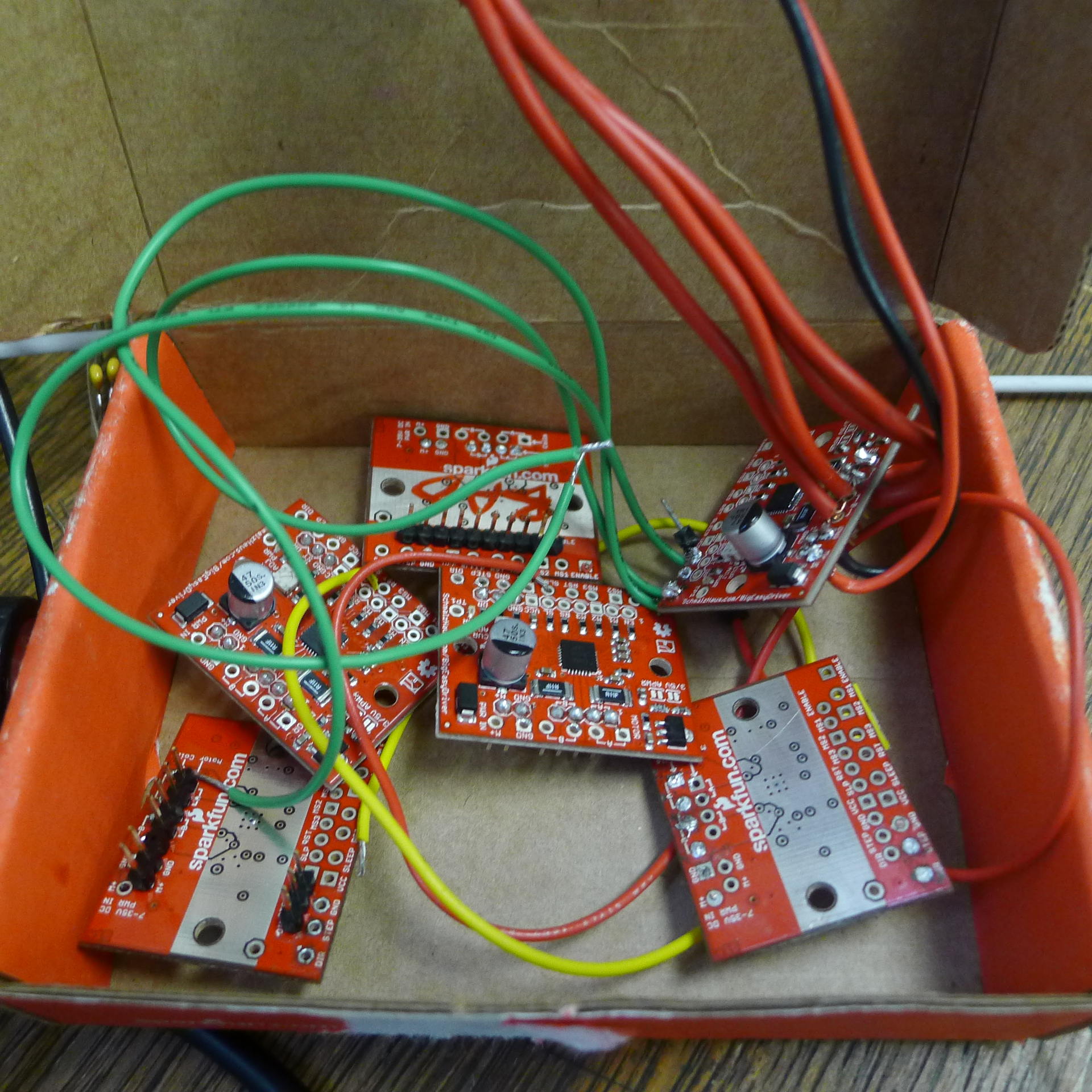
1st and foremost, if one is using a stepper, it is imperative that the stepper driver (and motor), not receive operating current for extended periods. Most stepper libraries (code) and motor drivers do NOT automatically put the driver and motor to "sleep" when not in use, meaning, even if the motor is not in motion, the default is to have current running to the motor (It is engaged) no matter. This will fry your shit easy, especially when the current is increased.
For the easy driver, there are two Pins you can wire in for enabling or disabling current to your driver/motor - these are "ENABLE" and "SLEEP". Connect them to Arduino and send them HIGH to disable current.
The second issue with my particular situation, is that the driver is automatically set to 1/16 micro-stepping mode, meaning that the frequency of pulses needed to move the motor is increased because each pulse represents a micro-step. For my purposes, I need to ground M1 and M2 to disable the microstepping function.
Another issue with my easy driver/motor combo, might lie in the input voltages from Arduino. It seems the board is extremely protected from overheating from too much load on the outputs...
The thing which kept failing on my boards was not the chip, the logic chip, but the voltage regulator. Therefore it might lie in my inputs, as it is the v.regulator which is fried.
In addition to making amendments to how the big easy is wired, I am also adding 1 microfarrad cap between step pin and ground and another between dir and ground. this may or may not prove useful in keeping my next round of drivers alive.
Therefore, I am beginning to build a transistor circuit to drive the stepper. I am basically building my own H-bridges out of transistors that are rated for way more current than my motor could ever pull.
The transistor is an ....
It is currently set to run a DC (ON/OFF).
Here is the schematic:

The digital out pin when set to low, connects ground and completes the circuit, allowing current to flow to the motor.
However, to drive a stepper, I need both forward and backwards and off.
Therefore, I really need to understand how a stepper functions inherently to know how to arrange the transistors.
So this is a nice article:
http://yertiz.com/cnc/steppermotor.pdf
SERIAL COMM WITH STEPPERS
I am building a matrix of stepper motors, it is important that each can switch roles dependent upon serial comm with a kinect. I had some major issues getting around the block functions which are how the stepper objects within the arduino works. I wanted a serialEvent as opposed to checking serial within the loop, as not to lose kinect data and also have a robust movement. This code basically checks for serial input as it goes through a loop, and each time it begins the loop it checks if the Master Index has changed and if the behavior of the current master stepper has completed.